

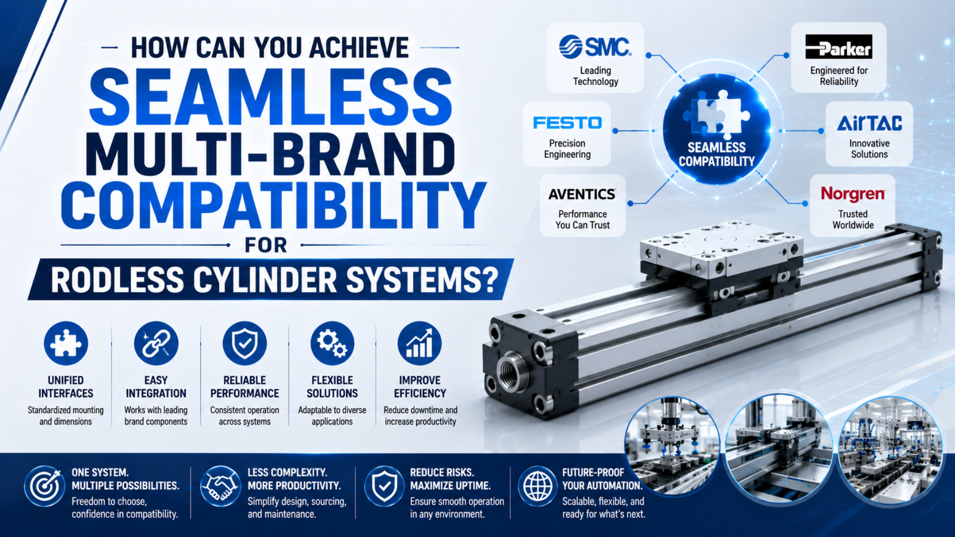
Multi-brand rodless cylinder compatibility is the verified ability of a replacement actuator to fit, carry the installed load, reproduce the required motion, connect to the pneumatic and electrical systems, and preserve the machine’s safe behavior. Matching a bore, stroke, or port thread proves only one part of that result. The practical route is a controlled replacement dossier, not a universal cross-reference. Compare the exact old and new order codes, drawings, load and moment limits, cushioning data, sensor interfaces, environmental options, and fault response. Then release the replacement only after an installed test under production load.
Key Takeaways
- Approve compatibility across 7 interfaces, not by brand name.
- Model-specific guide and moment limits govern the mechanical decision.
- Treat adapter plates, sensors, and thread conversions as engineered changes.
- Complete a loaded acceptance test before adding a replacement to the approved-parts list.
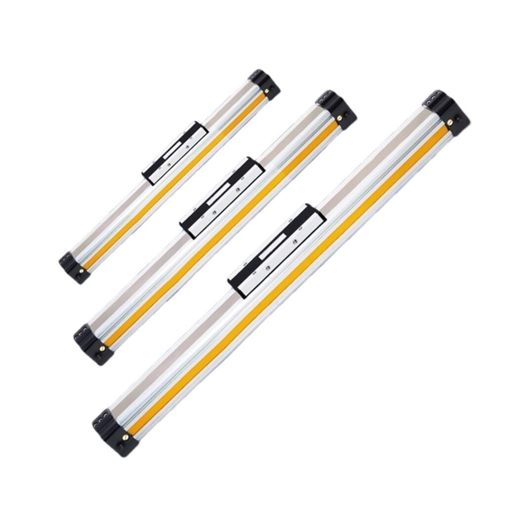
A similar profile can hide different carriage datums, guide capacities, port positions, sensor slots, and cushioning options.
For circuit-level valve and cylinder matching, use the separate mixed-brand pneumatic valve and cylinder checklist. This guide stays narrower: it addresses replacement of the rodless actuator itself.
What Does Multi-brand Compatibility Actually Mean for Rodless Cylinders?
ISO 4414:2010 applies to the design, construction, and modification of pneumatic systems and their components, including installation, adjustment, maintenance, and reliable operation (ISO 4414, 2010). Treat a cross-brand rodless cylinder replacement as a machine modification that needs documented application approval, not a percentage-based compatibility promise.
Four different statements are often compressed into the word “compatible”:
| Compatibility level | What it proves | What it does not prove |
|---|---|---|
| Connection compatibility | Fittings, ports, cables, and connectors can be assembled correctly | Required flow, signal logic, or loaded performance |
| Dimensional compatibility | The actuator fits the available envelope and mounting arrangement | Equal guide capacity, stiffness, or carriage datum |
| Functional compatibility | The installed drive reaches the commanded positions at the required speed | Safe behavior after air, power, or sensor loss |
| Approved application | The documented configuration passes the defined machine tests | Universal interchangeability in another machine |
Connection is only the first gate.
Mechanically coupled and magnetically coupled rodless cylinders belong to different operating architectures. Even within mechanically coupled products, a basic carriage, slide-bearing guide, cam-follower guide, recirculating-ball guide, and heavy-duty guide can have very different load paths. The family label is not the specification.
The strongest compatibility statement is deliberately narrow: “Replacement model X is approved for machine position Y with adapter drawing Z and acceptance record R.” That sentence gives maintenance a usable spare while preventing the approval from drifting into unrelated strokes, loads, orientations, or environments.
A Seven-Layer Rodless Cylinder Compatibility Dossier
SMC’s current MY1 range alone contains 5 standardized guide types, with bore availability extending from 10 to 100 mm depending on the variant (SMC MY1 web catalog, accessed 2026). That range shows why bore and stroke cannot serve as a complete cross-brand key.
Build one comparison row for each exact order code. Blank cells mean “not yet proven,” not “assumed equal.”
| Layer | Minimum evidence | Typical hidden mismatch |
|---|---|---|
| 1. Architecture | Mechanically or magnetically coupled; guided or externally guided | Similar envelope, different load-transfer method |
| 2. Geometry | Dimensioned drawing, CAD model, machine datums, clearances | Carriage height, end-cap length, port or adjuster access |
| 3. Load and motion | Mass, force direction, speed, acceleration, moments, duty cycle | Same bore, lower allowable roll or pitch moment |
| 4. Pneumatics | Pressure range, port standard, tube ID, flow controls, cushioning | Thread fits an adapter, but the air path or cushion does not |
| 5. Sensing and control | Slot type, switch model, voltage, PNP/NPN, pinout, logic | Sensor fits mechanically but does not switch the PLC input |
| 6. Environment | Temperature, corrosion, dust, washdown, cleanroom or ATEX option | Base model matches, required environmental option does not |
| 7. Service and release | Seal kit, band, switch, drawing revision, test record | Replacement works once but cannot be maintained consistently |
Unproven means stop.
The CAD-model review checklist is useful at layer 2, but CAD cannot prove catalog load limits or cushioning capacity. Keep the model, technical data, and acceptance test as separate evidence objects.
How Do You Compare Mounting Geometry Without Assuming Interchangeability?
Festo’s 2026 DGC-K catalog covers 8 piston diameters from 8 to 63 mm and publishes variant-specific forces, guide loads, moments, ports, and dimensions (Festo DGC-K, 2026). Cross-brand geometry should therefore be compared dimension by dimension against the exact variant, not inferred from nominal piston size.
Start with the machine datum that the payload or tooling actually references. Record the old and new values for:
- carriage datum height
- body width, carriage length, and the usable attachment surface
- overall length at the required stroke
- hole pitch, thread depth, counterbores, dowel holes, and the features that locate the drive instead of merely clamping it
- end-cap mounting points
- port positions, fitting envelope, and minimum tubing bend radius
- access to cushion needles, shock absorbers, switches, and band service points after guards and tooling are installed
- a full-stroke overlay showing the carriage, payload, cable chain, hard stops, guard openings, and the nearest fixed machine structures
The vertical centerline change created by an adapter is:
Here, is the installed carriage-height change, is the replacement carriage height, is adapter thickness, and is the original carriage height. Any nonzero result can change tooling alignment, belt tension, side load, guarding clearance, and sensor targets.
The datum moved.
Check tolerance as well as nominal size. Slotted plates can solve bolt spacing without controlling height, squareness, or repeatable location. Use dowels, shoulders, or machined reference edges when the tooling needs reproducible alignment. Record which feature locates the actuator and which fasteners only clamp it. Define the datum. In our experience, the most useful replacement drawing is often a one-page overlay of the old drive, new drive, adapter, payload datum, ports, and full-stroke envelope. It exposes inaccessible cushion screws and cable conflicts that a part-number cross-reference misses.
Rodless Cylinder Compatibility: Load and Moment Capacity After an Adapter Is Added
Parker’s 2025 OSP-P catalog states that its published load and moment data are based on speeds at or below 0.5 m/s and uses a combined load-moment factor limited to 1.0 (Parker Catalog 0900P-7, 2025). An adapter cannot preserve capacity unless the new load geometry passes the replacement catalog’s own rule.
An adapter plate can move the payload farther from the guide. That increases the applied moment even when the payload mass is unchanged:
In this relationship, is the applied moment, is the force acting on the carriage, and is the perpendicular offset from the guide reference. Include static weight, acceleration and deceleration forces, process forces, tubing drag, cable-chain reactions, and any overhung tooling.
Offset changes the load case.
For the Parker OSP-P horizontal-mounting method, the catalog expresses combined use as:
Here, , , and are applied moments about the catalog axes, is applied load, and each denominator is the matching catalog maximum for the selected size and guide. Use this equation only where the chosen manufacturer’s catalog specifies the same combination method and operating assumptions.
Festo’s DGC range illustrates why guide identity matters. Its 2026 overview publishes separate , , , , and values for compact, basic, plain-bearing, recirculating-ball, and heavy-duty variants (Festo DGC range, 2026). Do not transfer a limit from one guide variant to another.
For more detail on guide architecture and load paths, see the rodless-cylinder load-carrying mechanism guide.
How Do You Verify Ports, Flow, Speed, and Cushioning?
SMC’s MY1 protective-cover catalog lists operating pressure ranges from 0.1 or 0.15 MPa up to 0.8 MPa for several variants, with piston-speed limits that depend on the selected cushioning arrangement (SMC MY1W, 2024). Matching maximum pressure alone cannot prove equivalent motion.
Compare these pneumatic details for the exact old and new configurations:
| Item | Datasheet check | Installed check |
|---|---|---|
| Pressure | Minimum, normal, maximum, and proof pressure | Dynamic inlet pressure during the fastest loaded stroke |
| Port | Thread designation, size, location, sealing method | Correct fitting, seal, torque, access, and leak test |
| Air path | Valve flow, tube ID, length, fittings, flow controls, silencers | Loaded extend and retract times plus chamber pressure behavior |
| Cushion | Rubber bumper, air cushion, shock absorber, adjustment range | End impact, rebound, noise, and repeatability at worst-case mass and speed |
| Orientation | Horizontal, vertical, or inclined catalog conditions | Helping and overrunning loads in both directions |
Thread letters must be written completely. ISO 228-1:2000 covers parallel pipe threads where a pressure-tight joint is not made on the threads, so sealing requires external mating surfaces and a suitable seal (ISO 228-1, confirmed 2022). ISO 7-1 covers pipe threads where the pressure-tight joint is made on the threads (ISO 7-1, confirmed 2020). NPT is a different system covered by ASME B1.20.1. Never force an NPT male into a G or Rp port because the apparent engagement does not prove correct thread form, sealing, or remaining wall strength. The BSP, NPT, G, and R thread guide provides the identification details.
Thread identity comes before adapter selection.
The larger replacement port is not automatically beneficial if a reducer, narrow fitting, long tube, or exhaust silencer remains the controlling restriction. Measure stroke time at the required supply pressure and production load. Then check whether the new cushion or shock absorber can absorb the actual moving mass at that approach speed.
For cushion selection boundaries, use the separate fixed bumper versus adjustable air-cushion guide.
What Must Match on Sensors and Machine Controls?
Parker’s current OSP-P sensor catalog lists reed and electronic switches, including PNP and NPN options, and gives different mounting dimensions across OSP-P sizes 10 through 80 (Parker OSP-P Sensors, 2025). Mechanical fit in one sensor slot does not establish electrical or positional equivalence.
Verify the full sensing chain rather than treating the switch as a loose accessory:
| Interface | Evidence to compare |
|---|---|
| Sensing principle | Reed, solid-state magnetic, inductive, or position transmitter |
| Mechanical fit | Slot geometry, bracket, insertion direction, retention, and cable exit |
| Electrical supply | Voltage range, current consumption, polarity, and protection |
| Output behavior | PNP or NPN, normally open or normally closed, 2-wire, 3-wire, or 4-wire |
| Connection | Connector family, keying, pinout, cable length, and shielding |
| PLC input | Input type, input current, off-state leakage, filtering, and diagnostic logic |
| Position result | Switching point, hysteresis, repeatability, and overtravel margin |
Voltage is only one field.
Do not assume that “24 VDC” closes the comparison. PNP switches source current while NPN switches sink it. Two-wire reed switches can also behave differently from 3-wire electronic switches at the PLC input, especially where off-state leakage, surge protection, or minimum load matters. Mount and teach both end-position sensors with the machine depressurized and controlled against unintended motion. Then prove their signals during slow commissioning, normal production speed, load variation, and repeated stops. The sensor-failure analysis guide helps separate switch damage from magnetic, wiring, and PLC-input problems. Watch the edge cases.
Communication conversion belongs elsewhere unless the actuator actually includes a position transmitter, IO-Link device, valve terminal, or networked controller. Conventional rodless cylinders with two magnetic switches do not need a protocol gateway simply because the replacement brand changed.
Adapter Plates Are Controlled Machine Parts
ISO 4414:2010 explicitly includes modification, assembly, installation, adjustment, and maintenance within its pneumatic-system scope (ISO 4414, 2010). Treat each cross-brand adapter plate as a controlled part with a drawing number, material, tolerances, fastener specification, load basis, and revision status.
Release-ready adapter drawings should define the following controls:
| Drawing control | Required detail |
|---|---|
| Application identity | Machine position plus old and new actuator order codes |
| Datums | Mounting face, carriage reference, payload centerline, and stroke origin |
| Material | Alloy or steel grade, thickness, flatness, and surface treatment |
| Machined features | Hole sizes, thread engagement, counterbores, edge distances, and tolerances |
| Location method | Centering pins, shoulders, keys, or reference edges |
| Fasteners | Property class, quantity, tightening method, access, and retention |
| Load basis | Forces, moments, acceleration case, payload offset, and catalog limits |
| Service envelope | Clearance for fittings, tubes, switches, cushion adjusters, guards, and tools |
| Inspection | Measured characteristics, gauges, acceptance limits, and drawing revision |
The drawing travels with the spare.
From our work on replacement reviews, an adapter package is easier to maintain when the drawing names the actuator order code, machine position, and permitted revision. Loose plates in a spares cabinet cannot preserve those relationships.
The adapter is not a device that makes two brands universal. It is one controlled component in a specific load path. If the adapter changes carriage height, payload offset, support spacing, or end-stop location, the replacement calculation must use the modified geometry.
Avoid modifying the actuator rail or carriage unless the manufacturer explicitly permits it. Drilling can cut internal passages, reduce section strength, damage sealing surfaces, contaminate the drive, or remove a protected surface. Prefer reversible external adapters that can be inspected, replaced, and returned to the approved configuration. Include the adapter and actuator in the machine’s spare-parts record. If the original part becomes obsolete, the cross-reference should still point to the exact adapter revision, sensor kit, fittings, cushion arrangement, and validation report needed for installation. Prefer reversible interfaces.
How Should the Replacement Be Tested and Released?
ISO 4414:2010 addresses reliable operation in all intended uses as well as installation, adjustment, and maintenance (ISO 4414, 2010). Release testing must therefore cover production load, full stroke, normal controls, and foreseeable loss-of-energy states, not just a low-speed no-load movement on the workshop bench.
Use a test plan with recorded values and a named acceptance decision:
| Test stage | Record | Pass condition |
|---|---|---|
| Incoming inspection | Full order code, stroke, options, port and switch details | Matches the approved comparison dossier |
| Static installation | Datums, alignment, fastener torque, clearance, tube routing | Meets drawing and machine tolerances |
| Pneumatic integrity | Test pressure, leak locations, regulator setting | No unacceptable leakage or pressure instability |
| Slow functional cycle | Direction, sensor sequence, cushion engagement, interference | Complete stroke without binding or logic error |
| Loaded dynamic cycle | Cycle time, dynamic pressure, end impact, repeatability | Meets the machine requirement at worst-case load |
| Fault and restart | Air loss, power loss, sensor fault, restart sequence | Matches the documented safe and recovery behavior |
| Endurance observation | Defined trial count, temperature, fastener condition, band tracking | No trend requiring redesign or adjustment |
A bench stroke is not release.
We found that recording the first loaded cycles creates a better maintenance baseline than a simple pass label. Cycle time, dynamic pressure, sensor timing, impact behavior, and fastener condition give the next technician values to compare after service.
Use isolation and stored-energy controls appropriate to the machine before installation or adjustment. Do not put hands into the moving envelope to set sensors or cushions while unexpected motion remains possible.
Once the trial passes, update the bill of materials, maintenance instructions, CAD package, electrical drawing, PLC comments, spare-parts list, and cross-reference register. The facility cylinder-standardization guide explains how to keep approved platforms and engineered exceptions from drifting.
For a supplier RFQ, attach the old part number, photos of the nameplate and installation, dimensioned envelope, stroke, load and offset, speed, orientation, ports, switches, environment, and acceptance criteria. Brand and bore alone are not enough.
Rodless Cylinder Compatibility FAQs: What Should Buyers Ask?
SMC lists 5 MY1 guide types, while Festo publishes separate guide-load and moment data across several DGC variants (SMC MY1, accessed 2026; Festo DGC, 2026). These product structures explain why every buyer FAQ must return to the exact model and application.
Can a rodless cylinder with the same bore and stroke replace the original?
Not by those two values alone. Confirm coupling architecture, guide type, mounting datums, total length, carriage geometry, forces, moments, speed, cushioning, ports, sensors, environment, and fault behavior. The replacement becomes approved only after those records match the machine requirement and the installed unit passes its defined loaded test.
Are Festo, SMC, and Parker rodless cylinders dimensionally interchangeable?
Do not assume so. Their product families use different variant structures, dimension tables, guide capacities, options, ports, sensors, and ordering codes. Compare the exact old and new models using controlled drawings or CAD, then define any adapter as a separate engineered part with its own datums, load check, and inspection requirements.
Is a universal mounting plate enough to solve cross-brand compatibility?
No. The plate can convert a hole pattern or carriage height, but it can also increase payload offset and applied moment. It does not validate guide capacity, cushion energy, flow, switch logic, fault response, or environmental suitability. Recalculate with the final geometry and test the complete installed configuration. No plate is universal.
Can I reuse the original magnetic switches?
Only when the switch fits the new slot and its supply voltage, output type, wiring, connector, current limits, switching point, and PLC logic all match. Parker’s OSP-P literature, for example, lists both PNP and NPN electronic options. Mechanical fit alone cannot establish electrical or positional equivalence.
What should a supplier receive before proposing a replacement?
Send the full original order code, stroke, orientation, payload mass and offsets, speed, cycle rate, mounting and carriage dimensions, port and tube details, switch specifications, environmental requirements, photos, CAD or drawings, and acceptance criteria. This evidence lets the supplier identify exceptions instead of guessing from brand, bore, and stroke.
Sources and technical references
- ISO, “ISO 4414:2010 Pneumatic fluid power: General rules and safety requirements for systems and their components,” published 2010, confirmed current. Retrieved 2026-07-27 from
https://www.iso.org/standard/44790.html. - Parker Hannifin, “Catalog 0900P-7 Rodless Pneumatic Cylinders,” current catalog accessed 2025-2026. Retrieved 2026-07-27 from
https://www.parker.com/content/dam/Parker-com/Literature/Literature-Files/pneumatic/Literature/Actuator-Cylinder/0900/0900P_Rodless.pdf. - Parker Hannifin, “OSP-P Pneumatic Rodless Cylinders and Linear Guides: Sensors,” current catalog accessed 2025. Retrieved 2026-07-27 from
https://www.parker.com/content/dam/Parker-com/Literature/Literature-Files/pneumatic/parker_origa/ServicepartsandSensors.pdf. - Festo, “Linear drives DGC-K,” 2026/04 edition. Retrieved 2026-07-27 from
https://www.festo.com/media/catalog/202775_documentation.pdf. - Festo, “Linear drives DGC: Product range overview,” 2026/04 edition. Retrieved 2026-07-27 from
https://www.festo.com/media/catalog/204198_documentation.pdf. - SMC Corporation, “Mechanically Jointed Rodless Cylinder MY1,” current web catalog. Retrieved 2026-07-27 from
https://www.smcworld.com/webcatalog/en-id/air-cylinders/mechanically-jointed-rodless-cylinders/MY1-E. - SMC Corporation, “Mechanically Jointed Rodless Cylinder with Protective Cover MY1W,” current catalog. Retrieved 2026-07-27 from
https://www.smcworld.com/catalog/en/actuator/MY1_W-E/6-2-1-p1339-1365-my1w_en/data/6-2-1-p1339-1365-my1w_en.pdf. - ISO, “ISO 228-1:2000 Pipe threads where pressure-tight joints are not made on the threads,” confirmed 2022. Retrieved 2026-07-27 from
https://www.iso.org/standard/33777.html. - ISO, “ISO 7-1:1994 Pipe threads where pressure-tight joints are made on the threads,” confirmed 2020. Retrieved 2026-07-27 from
https://www.iso.org/cms/%20render/live/en/sites/isoorg/contents/data/standard/02/08/20819.html. - ASME, “B1.20.1 Pipe Threads, General Purpose, Inch,” 2013 edition reaffirmed 2018. Retrieved 2026-07-27 from
https://www.asme.org/codes-standards/find-codes-standards/b1201-pipe-threads-general-purpose-inch.