

Acoustic noise can affect a pneumatic system in three different ways. During long shifts and repeated fast cycles, it can expose workers to hazardous sound while also masking alarms and spoken warnings at the operator station. It may also signal changed air flow or component condition and reveal a new impact or vibration. Yet noise alone does not prove a failed cylinder, valve, or seal.
The useful question is not simply, “How loud is the machine?” Identify the event and measurement position first; then compare pressure and flow against stroke time and position while recording any simultaneous vibration change. This disciplined boundary prevents a hearing-safety assessment from becoming an unsupported diagnosis of machine performance.
Noise is evidence, not a verdict.
Key Takeaways
- NIOSH recommends an 85 dBA limit for an eight-hour occupational exposure, with allowable time halved for each 3 dB increase.
- A louder cycle may indicate several different faults, but sound alone cannot identify which one occurred.
- Verify every noise control against exhaust back pressure and cylinder speed. Recheck force margin, alarms, and safe machine motion too.
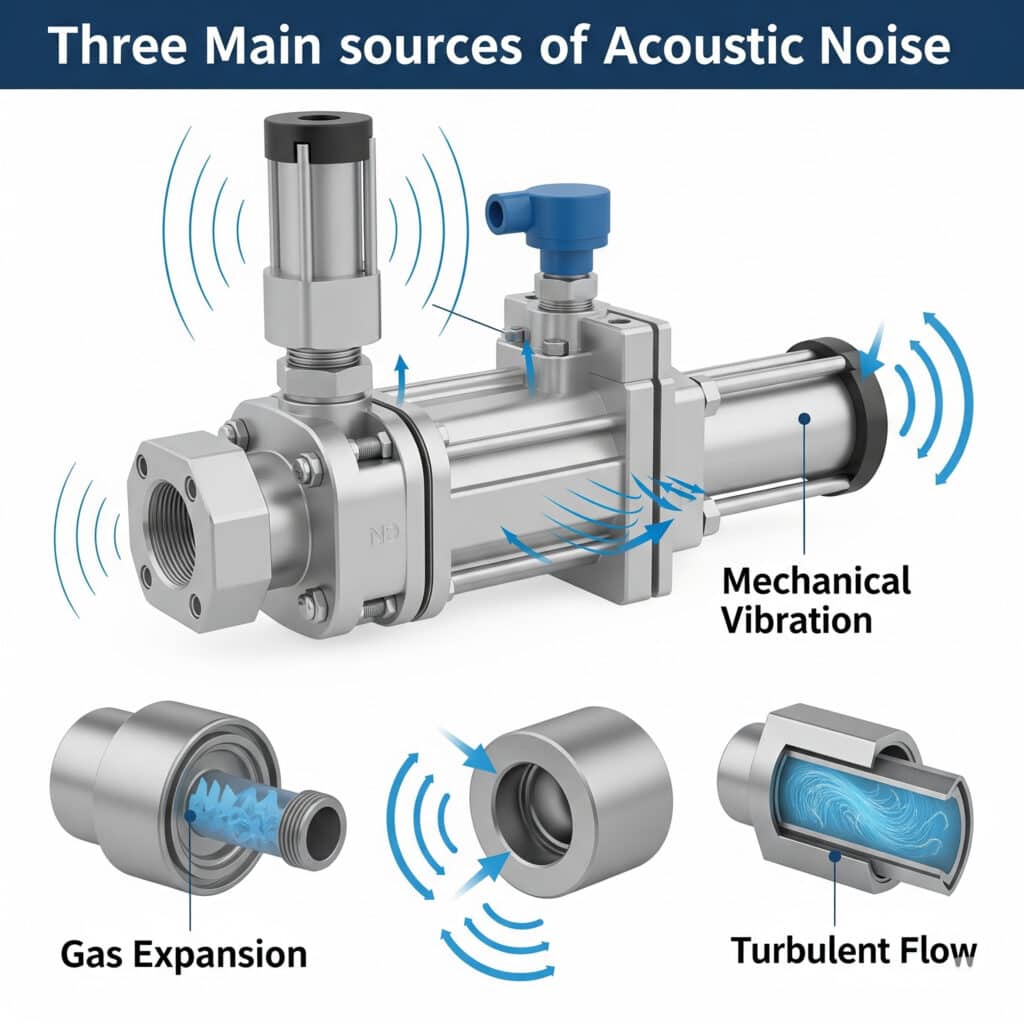
Pneumatic noise can begin in the air path or the mechanical structure. This source map is illustrative; the actual source must be confirmed under the machine’s operating conditions.
What Does Acoustic Noise Actually Change in a Pneumatic System?
NIOSH sets its recommended occupational exposure limit at 85 dBA averaged over eight hours and identifies repeated exposure at or above that level as hazardous (NIOSH, 2024). That exposure limit addresses hearing risk. It does not define acceptable valve flow, cylinder speed, positioning accuracy, or component life.
Noise can still affect production in practical ways:
- Worker exposure: Repeated high sound levels can damage hearing. Exposure depends on level, duration, repetition, and the worker’s location during the shift.
- Communication and awareness: High background noise can make speech, alarms, and warning signals harder to hear. NIOSH notes that reduced awareness can contribute to workplace incidents (NIOSH, 2024).
- Fault detection: A new hiss, knock, buzz, or ringing panel can reveal that the machine has changed, especially when compared with a healthy baseline.
- Motion performance: A clogged silencer or restricted exhaust may make a machine quieter while also raising back pressure and slowing an actuator.
- Maintenance workload: Intermittent leaks, loose brackets, worn cushions, and tubing impacts can generate sound before they create an obvious production stop.
In our experience reviewing pneumatic applications, the most useful first split is whether the concern is regulatory or diagnostic. The meter can show that a cycle changed, but it cannot identify a leak, valve exhaust pulse, cylinder impact, or vibrating guard panel on its own. Confirm the hypothesis with another measurement.
Sound Pressure, Sound Power, and Exposure Are Not Interchangeable
NIST uses 20 µPa as the reference sound pressure in air, while ISO 3744 determines sound power from measurements over a surface surrounding the source (NIST; ISO 3744:2025). These quantities describe different measurement boundaries, so a bare number followed by “dB” is incomplete.
Sound pressure level at a measurement point is defined as:
Here, is sound pressure level in decibels, is the root-mean-square sound pressure over the stated interval, and is 20 µPa in air. The result also needs a microphone position, frequency weighting, time response, operating event, and background-noise condition.
| Quantity | Appropriate use | Missing information if reported alone |
|---|---|---|
| dBA at a fixed point | Comparing sound at the same operator or test position | Daily exposure without time history |
| Personal noise dose or TWA | Assessing a worker’s exposure across tasks and locations | Which pneumatic component produced the sound |
| Sound power level | Comparing source emission under a defined test method | The level at a particular worker position |
| Peak or maximum level | Capturing short impacts or exhaust events | Exposure duration and event frequency |
| Spectrum or spectrogram | Separating tones, broadband flow, impacts, and changing events | Root cause without pressure, command, or vibration data |
OSHA’s general-industry rule illustrates why the distinction matters. It uses an 85 dBA eight-hour TWA as the hearing-conservation action level and a 90 dBA eight-hour TWA permissible exposure level, with a 5 dB exchange rate (OSHA 29 CFR 1910.95). NIOSH recommends 85 dBA for eight hours with a 3 dB exchange rate. These are exposure frameworks, not pneumatic component ratings.
Keep those boundaries separate.
Where Does Pneumatic Noise Come From?
SMC lists a 30 dB(A) noise-reduction value for specific AN-series silencers, which confirms that valve exhaust can be a major controllable source but also shows why attenuation must remain model-specific (SMC AN Series). Pneumatic system noise is the airborne and structure-borne sound produced by the complete installed machine, not just by its exhaust port.
Exhaust jets and internal restrictions
When a directional valve shifts, one actuator chamber fills while the other vents through the valve path and connected exhaust hardware. These passages can create broadband flow noise. The microphone result depends on pressure ratio and mass flow. Exhaust geometry also matters. So do downstream hardware and the surrounding room. Choked flow limits mass flow through a restriction; it does not assign a universal noise level. The related guide to choked flow in pneumatic systems explains that flow boundary in more detail.
Leaks
Continuous hissing during a commanded machine dwell may indicate air escaping from a fitting or tube after motion has stopped and the valve state should be stable. Valve seats and cylinder seals are other possibilities. An open blow-off point may sound similar. Local sound helps find the area but cannot confirm the leak. Use an isolation test; pressure decay; flow measurement; or a suitable ultrasonic survey.
Don’t assume every high-frequency sound is a leak. Small exhaust ports, pilot vents, and partially open flow controls can produce a similar hiss during normal operation.
Timing gives the first clue. Does the sound continue after the commanded motion ends?
Mechanical impact
End-of-stroke contact can produce a short and high-level event. So can a gripper jaw hitting a part or tubing striking a guard. Compare the sound with synchronized position and stroke-time records; then check cushion adjustment and actual speed against the moving load, supply pressure, external stops, and required end-of-travel behavior.
Reducing the sound without correcting the impact energy may only hide the symptom.
Structure-borne vibration
Valve manifolds, brackets, guards, and machine frames can transmit and radiate vibration. Small components may excite a large panel and make it seem like the original source.
Accelerometer data or a temporary damping test helps separate the excitation point from the radiating surface.
For valve-specific acoustic signatures and synchronized measurements, use the dedicated pneumatic valve noise guide.
When Does a Noise Change Point to a Performance Fault?
NIOSH uses a 3 dB exchange rate because a 3 dB increase represents twice the sound energy in its equal-energy exposure model (NIOSH, 2016). That logarithmic relationship makes small numerical changes important, but it still cannot identify a pneumatic fault without matched process data.
Sound energy is not fault identity.
Use a two-channel rule: treat noise as the first channel and require at least one independent process channel before declaring the cause. Pressure, flow, cycle time, position, valve command, or acceleration can provide that confirmation.
| Observed change | Possible explanation | Confirmation measurement |
|---|---|---|
| Continuous hiss during dwell | External or internal leakage | Isolation test, pressure decay, flow, or ultrasonic location |
| Louder exhaust pulse with normal motion | Changed pressure, flow, or exhaust geometry | Supply and exhaust pressure plus fixed-position sound |
| Quieter exhaust with slower cylinder | Clogged or undersized silencer | Pressure at silencer inlet and stroke time |
| Sharp knock at stroke end | Excess speed, cushion setting, load, or hard contact | Position, speed, cushion pressure, and moving mass |
| New tonal buzz | Panel, bracket, tube, coil, or manifold resonance | Acceleration and controlled touch or damping test |
| Noise changes when another actuator cycles | Shared supply or exhaust interaction | Synchronized pressure traces and command timing |
For example, suppose a machine develops a continuous hiss during dwell but its stroke time remains unchanged. First capture the sound from a fixed position and mark the valve command. Then isolate branches under the approved safety procedure and watch whether the sound stops with one branch. A pressure-decay or flow test can confirm whether air is actually being lost. If the hiss occurs only during a normal pilot vent and the isolated system holds pressure, treating it as a cylinder-seal failure would send maintenance in the wrong direction.
One of the most misleading patterns is the quiet, slow cylinder. Loaded silencers or restricted exhaust paths can reduce airborne discharge sound while trapping pressure in the venting chamber.
That back pressure opposes motion and can reduce usable force. The pneumatic back-pressure guide covers the force and speed checks.
The reverse can also happen. Louder exhaust may follow a maintenance change that restored flow through a previously clogged path.
The sound increased, but actuator performance improved. Measure before deciding which condition is healthy.
Context decides which result is better.
A Repeatable Pneumatic Noise Measurement Method
ISO 11201 can produce grade 1 or grade 2 emission sound-pressure results at workstations or other specified positions when its environmental and operating requirements are met (ISO 11201, confirmed 2026). Maintenance comparisons may be simpler, but they still need a fixed and documented test boundary.
Start by defining the decision:
- Worker exposure: Use a competent assessment based on the worker’s tasks, locations, and time history.
- Machine comparison: Hold the mounting and operating mode constant. Match load, cycle rate, pressure, exhaust hardware, background, and microphone geometry.
- Fault diagnosis: Trigger every channel from the same command or motion event.
- Source location: Move the sensor systematically or isolate one propagation path without changing the underlying machine condition. Record each temporary change so the comparison can be repeated.
Record at least the following:
- the reported sound quantity, frequency weighting, time response, averaging interval, instrument model, calibration status, and every other setting needed to repeat the measurement;
- exact microphone geometry, including distance from the source, direction, height, mounting method, and nearby reflective surfaces;
- background sound;
- valve command timing together with supply pressure, both actuator-port pressures, and cycle time;
- the complete actuator model together with bore, stroke, load, orientation, speed setting, and end-cushion condition;
- complete valve, fitting, tube, silencer, and exhaust-manifold details;
- the surrounding machine state plus enough repeated cycles to show whether the event is consistent.
Consider two recordings that both show 88 dBA. One was taken beside an exhaust port during a single valve shift; the other was measured at the operator position across a repeating production cycle. Those numbers are not interchangeable. Repeating the first test can compare component changes, while the second may contribute to an exposure assessment. Saving the microphone position and event timing prevents a later reviewer from treating them as equivalent. Adding synchronized chamber pressure and stroke time then shows whether the acoustic change coincided with a pneumatic restriction or motion problem.
Phone readings can be useful screening observations, but they are not automatically worker-dose assessments or product sound-power results. Their best maintenance use is repeatability: compare the same device, position, operating event, and environment with a documented healthy baseline.
Reducing Noise Without Restricting the Exhaust
OSHA requires a hearing-conservation program at an 85 dBA eight-hour TWA action level in general industry and identifies engineering or administrative controls above its 90 dBA eight-hour TWA PEL (OSHA). For pneumatic machinery, the best engineering control removes or weakens the source while preserving required motion and safety functions.
Use this order:
- Eliminate unnecessary air use. Stop open blow-off and repair confirmed leaks.
- Set the lowest reliable pressure. First check load, force margin, vertical holding, restart behavior, and the worst expected supply condition. Then reduce pressure and repeat the functional test.
- Control impact energy. Correct speed or cushion settings instead of covering an impact with acoustic material.
- Size the exhaust path. Compare the valve exhaust port, speed controller, fittings, tubing, shared manifolds, and silencer with peak exhaust demand.
- Select a suitable silencer. Use the exact model’s manufacturer flow and attenuation data. Measure pressure at the silencer inlet during motion after installation.
- Interrupt vibration paths. Identify the excitation source before stiffening or damping a panel.
- Separate people from residual noise. Where source controls cannot remove the remaining exposure, evaluate enclosures, barriers, distance, scheduling, and hearing protection under the applicable safety program.
Imagine that a new silencer reduces the measured sound but extends cylinder retraction time. A pressure sensor at the silencer inlet then shows that exhaust-side pressure remains elevated through most of the return stroke. The control worked acoustically and failed pneumatically. The next step is not to raise supply pressure. Check the silencer flow rating and service condition, then inspect the valve exhaust port and every downstream restriction. Repeat the same sound, pressure, and timing measurements after correction. The preferred result is quieter operation without the pressure trace or cycle-time penalty.
The dedicated pneumatic muffler selection guide explains element types, flow capacity, installation, and maintenance. When a meter-out circuit is involved, also verify the intended restriction direction using the meter-in versus meter-out guide.
After every change, rerun the same cycle. Record sound at the defined position, extend and retract time, peak exhaust-side pressure, end-of-stroke behavior, and position repeatability where relevant. Complete the check with alarm audibility and safe stopping behavior.
Quieter results are acceptable only when the machine still meets its force, speed, stability, and safety requirements.
What Data Should You Record for Troubleshooting or an RFQ?
ISO 6358-1 standardizes two main steady-flow characteristics for pneumatic components: sonic conductance and critical pressure ratio (ISO 6358-1). Port thread size alone therefore cannot describe valve or silencer capacity. Useful troubleshooting records combine component flow data with dynamic measurements from the installed machine.
| Data | Why it matters |
|---|---|
| Sound file plus measurement settings | Preserves timing and the reported acoustic quantity |
| Microphone position and machine layout | Makes before-and-after readings comparable |
| Supply and both actuator-port pressures | Separates supply loss from exhaust back pressure |
| Extend, retract, and dwell timing | Connects sound with the motion phase |
| Valve and manifold part numbers | Identifies tested flow characteristics and exhaust layout |
| Tube ID, length, fittings, and speed controls | Finds hidden local restrictions |
| Silencer model and service condition | Checks flow rating, contamination, and attenuation |
| Actuator bore, stroke, load, and orientation | Establishes force and motion margin |
| Cushion or external-stop settings | Explains end-impact events |
| Healthy and suspect cycle records | Provides a matched diagnostic baseline |
Preserve the relationship between the records, not only the individual files. Name each sound trace with the matching machine cycle and link it to the valve command, pressure traces, position record, and any accelerometer channel. Note every temporary change made during diagnosis. If a silencer was removed for an authorized test, identify the exact cycle and restore the approved exhaust control before normal operation. Photos should show sensor positions as well as component labels. This package lets another engineer reconstruct the test boundary, reject comparisons made under different conditions, and decide whether the next step belongs in occupational-noise assessment, pneumatic flow troubleshooting, mechanical inspection, or structural-vibration work. It also prevents a later maintenance shift from repeating an unsafe isolation test merely because the earlier record lacked context.
If the system cannot be isolated safely, do not remove exhaust components or defeat guards for a sound test. Use the machine’s risk-assessment and lockout procedures, then provide the collected data to the responsible machine builder or pneumatic engineer.
This article diagnoses the effect of noise changes in an installed machine. For a new project that needs an acoustic acceptance requirement before component selection, use the separate low-noise pneumatic system selection guide.
Pneumatic System Noise FAQs: What Should Engineers Check?
NIOSH recommends 85 dBA as an eight-hour occupational exposure limit, while OSHA uses separate action-level and permissible-exposure provisions (NIOSH; OSHA). The following answers keep worker exposure, machine emission, and pneumatic performance from being treated as the same measurement.
Does a louder pneumatic system always use more compressed air?
No. Continuous leaks can waste air and create noise, but louder exhaust pulses may simply reflect changed pressure, flow, port geometry, or microphone position. Confirm suspected waste with isolation, pressure decay, or flow measurement. Only matched operating cycles can support a link between a dB change and consumption.
Can a silencer make a pneumatic cylinder slower?
Yes. Silencers can restrict exhaust when undersized, clogged, oil-soaked, water-loaded, or connected through a narrow path. Measure inlet pressure during the stroke, then compare cycle time before and after a controlled service test. Never leave an exhaust port unsilenced as the permanent fix.
Is 85 dBA the legal limit for every pneumatic machine?
No. NIOSH’s 85 dBA value is a recommended eight-hour occupational exposure limit. OSHA’s United States general-industry rule uses 85 dBA as its hearing-conservation action level and 90 dBA as its eight-hour PEL. Product emission, worker exposure, local law, duration, and measurement method must be evaluated separately.
Can a frequency peak identify a failed cylinder seal or valve?
Not by itself. Frequency peaks help compare events and locate resonance, yet one band may contain exhaust flow, mechanical impact, a panel mode, tubing movement, or neighboring equipment. Confirm the source through synchronized command and process data. A controlled component change provides another check.
What should be checked after reducing pneumatic noise?
Recheck actuator speed, exhaust back pressure, force margin, end cushioning, position repeatability, warning audibility, and safe machine behavior. Keep the microphone position and operating cycle unchanged. This comparison is mandatory: quieter operation is not an improvement if it creates slow, weak, or unstable motion.