

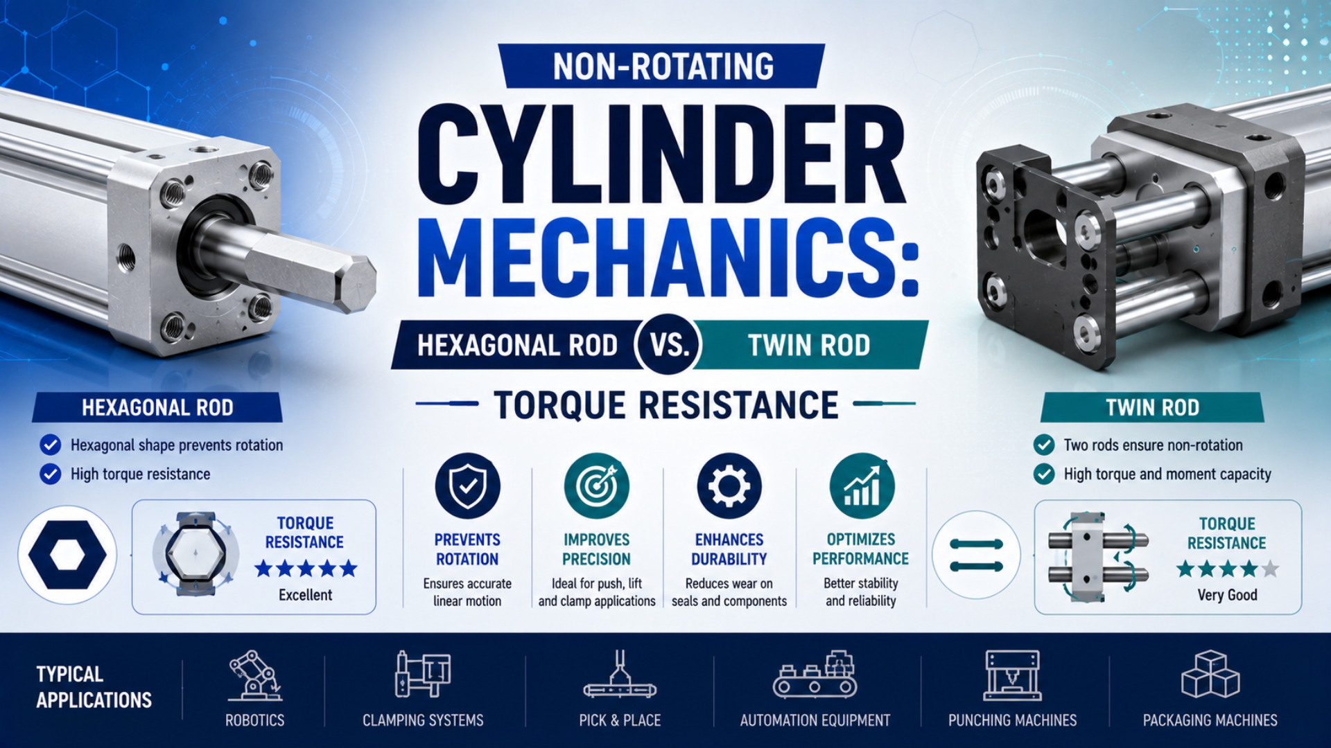
Hexagonal-rod and twin-rod cylinders resist rotation through different load paths, so neither architecture has a universal torque advantage. A hexagonal rod transfers torque through contact between its flats and a matching guide. Twin parallel rods create a force couple across separated bushings and an output plate. The exact catalog rating, not the rod label, decides capacity.
SMC illustrates the difference without supporting a generic multiplier. Its CJ2K hexagonal-rod series lists non-rotating accuracy of ±1.5° for 10 mm bore and ±1° for 16 mm bore, while its CXS2 dual-rod series states ±0.1° under the product’s specified conditions (SMC CJ2K; SMC CXS2, accessed July 26, 2026).
Key Takeaways
- SMC’s published examples range from ±1.5° for one hexagonal-rod size to ±0.1° for its CXS2 dual-rod construction.
- Non-rotating accuracy, allowable torque, angular stiffness, backlash, and side-load capacity are different specifications.
- Calculate applied moment first, then check the exact model, stroke, bearing, mount, speed, and load direction.
- Use an external guide when the cylinder’s anti-twist feature isn’t rated to carry the machine’s offset load.
The useful comparison isn’t “six flats versus two rods.” It is contact-guided torque transfer versus a separated bearing force couple. That distinction explains why a compact profiled rod can control orientation without being a side-load guide, and why a twin-rod cylinder can still deflect or bind when its mounting plate and external tooling are poorly aligned.
For a broader comparison of anti-twist pins, profiled rods, dual-rod cylinders, guided slides, and externally guided axes, see the non-rotating cylinder options guide. This article stays focused on hexagonal-rod versus twin-rod torque mechanics.
What Does “Non-Rotating” Actually Mean?
SMC gives the CJ2K hexagonal-rod series accuracy values of ±1.5° and ±1°, while CXS2 states ±0.1° for its dual-rod construction. Those figures describe angular orientation under catalog conditions. They do not mean zero motion, nor do they establish the same allowable torque, side load, or stiffness for every bore and stroke (SMC CJ2K; SMC CXS2, accessed July 26, 2026).
Non-rotating accuracy is the permitted angular deviation of the rod or output plate around the travel axis under a manufacturer’s stated test condition. It isn’t automatically the same as:
- Allowable rotational torque is the maximum applied torque permitted without damaging the guide or losing specified performance.
- Angular stiffness is the torque required to produce a unit of angular deflection within a stated range.
- Backlash or angular play: free angular movement caused by clearances before the opposite contact surface carries load.
- Repeatability: how closely the output returns to the same angle after repeated cycles.
- Side-load capacity: the permitted force perpendicular to the travel axis.
- Pitch and yaw moment capacity: allowable moments about axes other than the rod’s rotation axis.
This distinction matters at the process point. A rod may return to a repeatable unloaded angle yet twist farther when an offset gripper contacts a part. Conversely, a cylinder may remain within its allowable torque while the machine bracket flexes enough to miss the process tolerance. The accuracy-versus-repeatability guide explains why those acceptance terms can’t be exchanged.
Two Load Paths: Profile Contact and a Bearing Force Couple
SMC states that the CJ2K rod does not rotate because of its hexagonal shape, while Parker describes P1F-R and P1F-Q as twin-rod versions for non-rotating handling and packaging applications. The two products reach a similar functional result through different reacting surfaces (SMC CJ2K; Parker P1F, accessed July 26, 2026).
In a hexagonal or otherwise profiled rod, applied torque first consumes clearance between the rod and guide. Contact then develops on opposing faces or edges. Local pressure, guide length, material, surface treatment, lubricant, contamination, and accumulated wear determine the response.
In a twin-rod cylinder, the output plate tries to rotate both rods. The separated rod bushings develop opposing transverse reactions, creating a force couple. Rod bending, bearing clearance, plate stiffness, body stiffness, mounting flatness, and the distance between effective reaction lines all contribute to angular deflection.
How Does a Hexagonal Rod Resist Torque?
SMC’s current CJ2K sheet identifies a hexagonal rod as the anti-rotation mechanism and gives ±1.5° and ±1° accuracy for its two bores. A separate SMC CQSK catalog limits allowable rotational torque to 0.04 N·m for 12 and 16 mm bores, 0.2 N·m for 20 mm, and 0.25 N·m for 25 mm (SMC CJ2K; SMC CQSK, accessed July 26, 2026).
Those values are useful because they expose the danger in a generic “5 to 15 N·m” claim. A profiled rod’s shape prevents free rotation, but the small internal guide can still deform. SMC specifically warns that rotational torque can deform the non-rotating guide and compromise accuracy.
The load sequence is:
- The external tool applies torque around the rod axis.
- Initial angular movement takes up guide clearance.
- One or more rod faces contact the mating guide.
- Opposing contact reactions transfer torque into the cylinder body.
- The guide and rod deform elastically; excessive load can create permanent set or accelerated wear.
Six flats do not mean six faces share load equally. Manufacturing tolerances and elastic deformation usually bring selected regions into contact first. Edge radii, guide length, surface finish, hardness, lubricant, debris, and temperature alter the pressure distribution.
The published torque limit also isn’t a side-load rating. A long gripper arm can apply torque plus a bending moment at the rod bushing. If both loads exist, the cylinder may need an external guide even when the axial anti-rotation feature appears adequate. The side-loading guide covers the separate rod-bearing and seal consequences.
How Does a Twin-Rod Cylinder Resist Torque?
SMC attributes ±0.1° non-rotating accuracy to the dual-rod construction of CXS2, whose basic series covers 6 to 32 mm bores. Parker’s P1F-R/Q catalog, covering larger ISO-cylinder variants, provides bore- and stroke-dependent transverse and torque-moment load charts rather than one universal twin-rod torque value (SMC CXS2; Parker P1F, accessed July 26, 2026).
When an applied torque is reacted by an ideal force couple with effective spacing , the first-order reaction magnitude is:
Here, is the opposing reaction at each side of the idealized couple in newtons, is applied torque in newton-metres, and is the perpendicular spacing between effective reaction lines in metres. The relationship explains the geometry. It does not calculate the cylinder’s allowable torque.
Increasing effective spacing reduces the required bearing reaction for the same applied moment. Yet the catalog rating can still be governed by rod bending, bushing pressure, output-plate deflection, body stress, fasteners, stroke position, or dynamic impact. That’s why a visual measurement of rod center distance cannot replace the manufacturer’s load chart.
Be careful with terminology. A twin-rod cylinder normally has two parallel rods or piston assemblies that constrain an output plate. A double-rod cylinder may instead have one piston rod extending from both ends of a common piston. The latter balances effective areas or provides a second rod end, but it doesn’t automatically create the same parallel-rod force couple.
Why Doesn’t Rod Spacing Alone Give a Torque Rating?
Parker supplies separate transverse and torque-moment load graphs for its P1F twin-rod cylinders, with curves changing by bore and stroke. That presentation is the correct engineering pattern: spacing affects the internal force couple, but usable capacity also depends on rod diameter, guide length, bearing design, plate stiffness, mounting, and operating condition (Parker P1F, accessed July 26, 2026).
Angular stiffness can be expressed over a stated linear range as:
Here, is torsional stiffness, is applied torque, and is angular deflection in radians. If backlash exists, measure it separately before fitting a stiffness slope. A cylinder can have low free play but limited load capacity, or high stiffness after contact but too much initial angular clearance for the process.
Stroke matters because longer exposed rods bend more under the transverse reactions that form the force couple. The output plate and mounting face also rotate. If a specification reports only an unloaded angle at one stroke position, it doesn’t establish the installed tool angle at full extension.
Speed and stopping behavior create another boundary. CXS2 lists maximum piston speed of 800 mm/s and allowable kinetic energy of 0.016 J for the series listing. Those values are separate from its ±0.1° non-rotating accuracy. Passing the angle specification doesn’t mean the cylinder can absorb every end-of-stroke event.
Rod spacing is best treated as an internal load-distribution variable, not a capacity claim. It tells you how a given torque becomes bearing reactions. Only the complete product model tells you whether the rods, bearings, plate, body, mounting, and cushion can carry those reactions throughout the stroke.
Worked Example: Convert an Offset Force into Applied Torque
ISO 8140 notes that rod-end clevises mechanically transmit cylinder force, while the actual tool often introduces an offset from the actuator datum. Before comparing anti-rotation architectures, convert the defined transverse or process force into a moment at the relevant guide axis (ISO 8140:2018, accessed July 26, 2026).
For a force acting perpendicular to an offset:
Here, is applied moment in newton-metres, is the force component perpendicular to the moment arm in newtons, and is the perpendicular distance from the selected guide datum to the force line in metres.
Suppose a process applies 35 N at a perpendicular offset of 80 mm:
The 2.8 N·m result is load demand, not an actuator rating. It already exceeds the 0.04 to 0.25 N·m examples in SMC’s CQSK table, so that specific compact profiled-rod family would not be accepted for this load. Another profiled-rod series might differ, but it needs its own documented rating.
Now consider an ideal twin-rod reaction spacing of 60 mm:
Each side of the ideal force couple carries about 46.7 N in opposite directions. Continue with the selected twin-rod manufacturer’s stroke-dependent chart, bearing type, plate deflection, mounting, speed, and safety method. Don’t compare 46.7 N directly with cylinder thrust; they act through different paths.
If the force comes from acceleration, determine it from the effective mass and measured or specified acceleration. If gravity, process contact, hose pull, and acceleration act together, resolve their directions and worst credible timing. The eccentric-load guide provides the wider free-body-diagram context.
Hexagonal Rod vs. Twin Rod Torque Resistance: Which Specifications Matter?
SMC’s published examples show why architecture labels are insufficient: CJ2K gives ±1.5° or ±1° non-rotating accuracy, CQSK gives 0.04 to 0.25 N·m allowable torque across four bore sizes, and CXS2 states ±0.1° for its dual-rod construction. These are different metrics from different series (SMC CJ2K; SMC CQSK; SMC CXS2, accessed July 26, 2026).
| Selection item | Hexagonal or profiled rod | Twin parallel rods | Evidence required |
|---|---|---|---|
| Primary torque path | Contact between rod profile and matching guide | Force couple across separated rods and bushings | Section drawing and manufacturer description |
| Angular accuracy | Guide clearance plus elastic deformation | Bearing clearance, rod bending, plate and body deformation | Exact load state and stroke position |
| Allowable roll torque | Series-specific guide limit | Series-specific roll-moment or torque chart | Exact model, bore, stroke and bearing |
| Side force and pitch/yaw moments | Often separate or restricted | May be published separately from roll torque | Axis-specific load chart |
| Wear sensitivity | Profile corners, flats and guide surfaces | Rod bushings, guide surfaces and output plate | Lubrication and inspection instructions |
| Mount sensitivity | Rod-guide alignment and tool concentricity | Body flatness, rod parallelism and plate alignment | Installation drawing and datum scheme |
| Best use | Compact orientation control within rated torque | Output plate needing stronger angular constraint | Process tolerance and measured load |
| Escalation path | External guide or guided cylinder | Wider guided slide or external rail | Combined load and deflection review |
Festo’s DPCA catalog separates the anti-twist option from an additional PTFE piston guide. That product structure reinforces an important boundary: anti-twist protection and higher transverse-load guidance are not interchangeable functions (Festo DPCA, 2023; accessed July 26, 2026).
ISO 15552:2018 remains useful for basic, mounting, and accessory dimensions across its specified 32 to 320 mm bore range and 1,000 kPa series. It was confirmed current in 2025. The standard supports interchangeability, but it does not assign a universal torque capacity to a twin-rod variant (ISO 15552:2018).
How Do Wear, Clearance, and Mounting Change Accuracy?
SMC warns that applying rotational torque beyond the intended range can deform a non-rotating guide and compromise accuracy. Parker’s twin-rod installation section likewise presents allowable transverse and torque-moment load as bore- and stroke-dependent. Accuracy therefore changes with load, wear, stroke position, and installation, not just the new-cylinder geometry (SMC CQSK; Parker P1F, accessed July 26, 2026).
For a profiled rod, watch for polished flats, corner wear, fretting debris, stick-slip, contamination embedded in the guide, and increasing free angular movement. Don’t apply rod-end tightening torque through the internal anti-rotation guide. Hold the manufacturer’s defined wrench flats and follow its assembly instructions.
For twin rods, check rod parallelism, bushing clearance, uneven lubrication, plate flatness, fastener preload, and mounting-face distortion. A rigid tool that bridges the output plate to a second external guide can create a closed tolerance loop. The result is binding, not extra precision.
In our experience reviewing pneumatic applications, the quickest useful test is to mark the process datum, then measure angular movement at retracted, mid-stroke, and extended positions under both torque directions. That separates free play from load-dependent deflection and often reveals a flexible bracket or tooling plate before the cylinder is blamed.
Record a baseline when the machine is new. Repeating the same torque-angle test during maintenance turns “it feels loose” into a trend. If the angle changes sharply at one stroke position, inspect alignment and rod straightness. If free play grows steadily everywhere, inspect the guide and bearing surfaces.
When Should You Use an External Guide Instead?
Festo lists anti-twist protection and an additional piston guide as separate DPCA options, while Parker publishes stroke-dependent twin-rod load curves. Both sources point to the same decision: use a dedicated guide when offset force, pitch/yaw moment, deflection, shock, or process precision exceeds the selected cylinder’s documented internal guidance (Festo DPCA; Parker P1F, accessed July 26, 2026).
Choose an integrated guided cylinder, pneumatic slide, or external linear rail when:
- the tool center is far from the rod or plate datum;
- process contact creates side force in addition to roll torque;
- the payload produces pitch or yaw moment;
- angular accuracy must hold under load, not only in an unloaded catalog test;
- a long stroke makes rod bending significant;
- the machine already has a linear guide that can carry the moments;
- loss of orientation could create a safety or collision hazard.
Let one guide define the motion datum. Couple the cylinder so it can supply axial thrust without fighting the machine guide. A floating joint can accommodate permitted misalignment, but it doesn’t add moment capacity. See the side-load mitigation guide for that architecture.
A rodless actuator isn’t automatically a solution either. Magnetic or mechanical coupling transfers thrust, while an integral or external carriage guide must carry roll, pitch, and yaw. Check the exact guide ratings and support spacing.
A Practical Selection and Validation Procedure
SMC’s CXS2 listing combines ±0.1° non-rotating accuracy with 800 mm/s maximum piston speed and 0.016 J allowable kinetic energy. Three separate values are required because orientation, speed, and stopping energy govern different failure modes. A complete selection must pass every relevant catalog limit (SMC CXS2, accessed July 26, 2026).
Use this worksheet before selecting a cylinder:
| Input | What to record | Why it matters |
|---|---|---|
| Process datum | Where angle and lateral position are measured | Prevents measuring the cylinder while ignoring flexible tooling |
| Torque demand | Force, perpendicular offset and direction | Establishes roll moment about the travel axis |
| Other moments | Pitch and yaw from payload and process contact | May require a guided slide rather than anti-twist only |
| Stroke positions | Retracted, process point and extended | Rod and mount compliance change through travel |
| Motion | Speed, acceleration, cycle rate and stopping method | Changes dynamic force and kinetic energy |
| Catalog identity | Manufacturer, series, bore, stroke, bearing and option | Keeps ratings tied to the configured product |
| Environment | Dust, washdown, temperature and lubrication | Changes wear and guide friction |
| Acceptance limit | Maximum angle, backlash and deflection under load | Turns “non-rotating” into a testable requirement |
Test the chosen unit in both torque directions because clearance and mounting asymmetry can produce different results. Apply the load at the real tooling point. Record angle before load, under steady load, after unloading, and after representative cycling.
If orientation is important to the process, measure at the tool, not only at the rod. Position sensing confirms piston or carriage travel, but it does not measure tool twist. The cylinder position-sensing guide explains that functional boundary.
Non-Rotating Cylinder Mechanics FAQs
SMC’s catalog examples span ±1.5° for a 10 mm CJ2K hexagonal-rod cylinder, ±1° for its 16 mm version, and ±0.1° for the CXS2 dual-rod construction. These are product-specific values, so the answers below keep torque, angle, side load, and installation evidence separate (SMC CJ2K; SMC CXS2, accessed July 26, 2026).
Is a twin-rod cylinder always more torque-resistant than a hexagonal-rod cylinder?
No. SMC states ±0.1° for CXS2 dual-rod construction, but that angle isn’t a universal torque rating. A larger profiled-rod series could permit more torque than a small twin-rod model. Compare allowable roll torque, stroke, bearing, angular deflection, side loads, speed, and impact for the exact configured products.
Does a hexagonal rod distribute torque equally across all six flats?
No. The hexagonal geometry blocks free rotation, but tolerances and elastic deformation bring selected faces or edges into contact first. SMC’s CQSK limits allowable torque from 0.04 to 0.25 N·m across its listed bores, confirming that the guide design and size, not the number of flats alone, determine capacity.
Can I calculate twin-rod torque capacity from rod spacing?
No. The relation estimates the ideal bearing force couple created by an applied torque. Parker instead publishes stroke- and bore-dependent load charts because rods, bushings, plate stiffness, body, mounting, and deflection also govern capacity. Use spacing to understand reactions, then use the exact catalog to approve the cylinder.
Is non-rotating accuracy the same as angular backlash?
No. CJ2K’s ±1.5° or ±1° catalog values describe non-rotating accuracy under stated product conditions. Backlash is free movement through clearance before opposing surfaces carry load, while stiffness describes additional deflection under torque. Request the applicable test condition and measure both torque directions at the installed process datum.
Does ISO 15552 certify the torque resistance of twin-rod cylinders?
No. ISO 15552:2018 covers basic, mounting, and accessory dimensions for interchangeability across its specified 32 to 320 mm bore, 1,000 kPa cylinder series. It was confirmed current in 2025, but it doesn’t assign universal roll-torque, angular-accuracy, side-load, or fatigue ratings to twin-rod variants.
Sources and Technical References
- SMC, Air Cylinder: Non-Rotating Rod Type, Series CJ2K. Hexagonal rod mechanism, non-rotating accuracy, stroke, speed, and kinetic-energy data. Retrieved July 26, 2026.
- SMC, Compact Cylinder: Non-Rotating Rod Type, Series CQSK. Allowable rotational torque and guide precautions. Retrieved July 26, 2026.
- SMC, Dual Rod Cylinder CXS2. Dual-rod construction, non-rotating accuracy, speed, kinetic energy, bore, and bearing data. Retrieved July 26, 2026.
- Parker, P1F ISO Pneumatic Cylinders. P1F-R/Q twin-rod construction, dimensions, and transverse/torque-moment load charts. Retrieved July 26, 2026.
- Festo, Compact Cylinders DPCA. Anti-twist and additional piston-guide options. Published May 2023; retrieved July 26, 2026.
- ISO 15552:2018, Pneumatic Cylinders with Detachable Mountings. Basic, mounting, and accessory dimensions for interchangeability; confirmed 2025. Retrieved July 26, 2026.
- ISO 8140:2018, Mounting Dimensions of Rod-End Clevises. Rod-end clevis dimensions and force-transmission scope. Retrieved July 26, 2026.
Conclusion: Select the Rated Load Path, Not the Rod Count
SMC’s examples range from ±1.5° for one hexagonal-rod model to ±0.1° for a dual-rod series, while Parker uses bore- and stroke-specific torque-moment charts. Those formats show why no fixed 3-to-5-times multiplier can compare every hexagonal-rod and twin-rod cylinder.
Calculate the applied torque at the real process datum. Then compare allowable torque, angular accuracy, backlash, stiffness, side load, stroke, speed, stopping energy, mounting, and environment for the exact product. If the internal anti-rotation mechanism isn’t rated to carry the complete load, move the moments into a guided slide or external linear guide.
For help reviewing a cylinder model, load case, or guide arrangement, send the series, bore, stroke, tooling offset, load directions, and required angular limit through the technical contact page.