

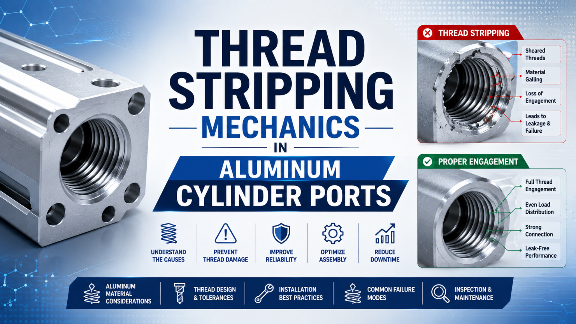
Thread stripping mechanics are the load-transfer and material-failure processes that remove usable thread from an aluminum cylinder port. Local shear or bearing stress eventually exceeds what the engaged female threads can carry. Excessive taper interference is one trigger. Others include incorrect straight-thread torque, cross-threading, damaged geometry and repeated movement. No safe universal rule converts a steel-port torque into an aluminum-port value.
Start with the thread form. ASME B1.20.1 covers dimensions and gaging for NPT plus related inch pipe threads (ASME, 2013, reaffirmed 2018). Straight-thread ports use another sealing mechanism. Mixing these installation rules is a direct route to a damaged cylinder head.
Key Takeaways
- Identify the port thread first.
- Match the installation method to the actual sealing design.
- Parker specifies 2-3 turns from finger tight for common 1/8 through 3/4 NPTF fittings.
- Calculate parent-thread pullout only from the actual material, engagement length, thread geometry and friction assumptions.
- Specify an insert only after confirming boss wall, nearby passages, corrosion control, tooling, gaging and the final pressure test.
Compare tapered and parallel connections in the cylinder port thread selection guide.
Why Must You Identify the Port Thread Before Choosing Torque?
ASME B1.20.1 covers five inch pipe-thread families (ASME, 2013, reaffirmed 2018). NPT, NPSC and NPSM are among them. A tapered pipe thread is a connection whose diameter changes along its axis. NPT sealing depends on thread interference plus sealant. Many straight-thread ports instead rely on a separate O-ring or bonded seal. As an NPT or NPTF male fitting advances, its taper becomes progressively tighter inside the female port. Additional rotation changes radial interference plus engaged position. It also changes stress in the aluminum boss. Resulting torque reflects thread geometry. Surface condition affects it too. So do sealant and material pairing.
Straight-thread fittings behave differently. Their threads generate axial clamp load. A separate O-ring or defined seat normally contains the air. Specified torque therefore belongs to a particular stud end. Its seal arrangement and port standard matter too. Substituting an NPT value is not a conservative shortcut.
| Port connection | Primary sealing mechanism | Correct installation reference | Main stripping risk |
|---|---|---|---|
| NPT or NPTF tapered thread | Thread interference plus compatible sealant | Manufacturer turns from finger tight and engagement checks | Excessive radial interference or damaged taper |
| BSPT tapered thread | Taper interference plus specified sealant | Manufacturer TFFT for the exact fitting | Mixing BSPT and NPT or overtightening |
| BSPP or G straight thread | O-ring, bonded seal or sealing face | Component-specific torque | Excess clamp load or wrong seal geometry |
| Metric ISO straight stud end | O-ring against a defined port seat | Exact ISO stud-end and fitting table | Applying a generic metric bolt torque |
For more context, this ASME B1.20.1 overview explains why nominal size alone does not define the finished joint.
What Do Thread Stripping Mechanics Reveal About Aluminum Ports?
NASA’s aluminum fastener study uses a pullout model with a safety factor of 3 (NASA/TM-2017-219475, 2017). Its tables exclude structural plus vibration loading. A useful core principle remains: parent-thread capacity depends on shear strength multiplied by pitch diameter and effective engagement rather than a material name alone.
For a straight internally threaded fastener, the study expresses allowable pullout load as:
is the modeled pullout load. The symbol represents thread pitch diameter. Parent-material shear strength is . Effective engagement is the usable contact length represented by . In this model, the denominator applies the study’s safety factor. Use the equation to understand a machined straight thread, not to set NPT fitting torque.
Five mechanisms usually combine at a damaged pneumatic port:
Parent-thread shear: The fitting transfers load into the female aluminum thread flanks. Too little effective engagement or an oversized tapped hole reduces the load-carrying area.
Excessive taper interference: An NPT fitting acts like a wedge. Each additional turn expands the female port region and raises local stress around the boss.
Cross-threading: An angled fitting loads the first thread segments instead of sharing contact around the circumference. The installer may mistake this abnormal resistance for normal taper engagement.
Galling and surface damage: Adhesive wear or torn material raises friction. More wrench effort then produces less predictable advancement and may remove the remaining thread crest.
Cyclic movement: A heavy valve, unsupported tube or vibrating hose applies bending at the port. Micromotion can loosen the joint, fret the contact surfaces and turn a marginal installation into a fatigue problem.
A stripped port is rarely diagnosed by the final wrench reading alone. The evidence chain begins with the thread standard and gage condition, then follows engagement, sealant, fitting support and operating movement. Even a normal-looking torque record cannot prove that the fitting started square or that the female taper was in tolerance.
The thread-root stress concentration analysis provides additional context for cracks that begin below an apparently intact first thread.
Why Does a Universal Aluminum Torque Table Fail?
NASA’s current mechanical fastener guidance uses an average torque coefficient of 0.30 for cleaned dry fasteners and 0.18 for lubricated fasteners, while requiring parent-thread tear-out to be checked separately (NASA Mechanical Fastener Torque Guidelines, 2020). A single torque number cannot absorb that friction change, much less a change in thread form or sealant.
For straight fasteners, a familiar relationship is:
is tightening torque. The empirical torque coefficient is . Axial preload is . Nominal fastener diameter is . NASA’s Fastener Design Manual explains that most applied torque becomes thread plus bearing friction (NASA RP-1228, 1990). Only a portion becomes useful preload.
This relationship is valuable for a controlled bolted joint. A tapered pipe connection is different. Its fitting advances into an interference geometry. Sealant changes friction. The port may seal before or after a particular wrench angle. Parker therefore says not to assemble tapered pipe fittings to a specific torque (Parker, accessed 2026). Thread quality, materials and sealant change the result.
Practically, a fixed multiplier cannot convert steel NPT torque into a safe aluminum NPT value. Use the cylinder and fitting manufacturers’ approved procedure. If the exact material combination is outside that procedure, qualify it through controlled assembly and pressure testing.
| Variable | What it changes | Evidence needed |
|---|---|---|
| Thread form and tolerance | Advancement, interference and contact position | Drawing, thread callout and gage record |
| Sealant or lubricant | Friction, sealing and cure behavior | Product instructions plus compatibility |
| Fitting material and finish | Galling tendency and surface friction | Exact part specification |
| Aluminum alloy and temper | Parent-thread shear and deformation | Material certificate or drawing requirement |
| Port boss geometry | Expansion stiffness and remaining wall | Section drawing and tolerance stack |
| Reuse history | Thread deformation and seal quality | Service record and visual inspection |
How Should NPT and NPTF Cylinder Ports Be Assembled?
Parker’s tapered-thread table specifies 2-3 turns from finger tight for 1/8, 1/4, 3/8, 1/2 and 3/4 NPTF fittings made from steel, stainless steel or brass (Parker, accessed 2026). This is a fitting-family procedure, not permission to apply the same turns blindly to every aluminum cylinder port.
Use this controlled sequence:
- Confirm both thread identities. Never identify a port by appearance alone.
- Inspect the female port carefully. Find torn crests, embedded tape, corrosion and previous over-advancement before a new fitting hides the evidence.
- Check the male fitting. Reject damaged or contaminated threads. Compare its callout with the cylinder drawing and confirm enough access for square entry.
- Apply approved sealant. Follow its coverage and cure instructions.
- Start entirely by hand. The fitting should reach a repeatable finger-tight reference without rocking, early binding or visible angular entry. Stop and investigate any abnormal resistance.
- Mark the reference position. Count the specified wrench turns rather than relying on feel.
- Verify the final state. Record engaged position and alignment. Never back off a tapered fitting merely to improve orientation unless the approved procedure explicitly allows that movement.
- Pressure-test before release. Use the cylinder manufacturer’s leak-test pressure, isolation period, permissible leakage and inspection method before reconnecting the actuator to the machine.
Parker notes that a normally assembled tapered connection commonly has 3.5 to 6 threads engaged. A result outside that range can indicate under-tightening, over-tightening or out-of-tolerance threads. That observation is more diagnostic than a copied torque value because it checks what the connection actually did.
Do not use added wrench force as a leak-repair method. Remove pressure, inspect the thread and apply the correct sealing procedure. Continued tightening can trade a small leak for permanent port damage.
How Should Straight-Thread Ports Be Treated Differently?
Parker’s ISO 6149 stud-end table assigns 10 N·m to one M8x1 configuration and 20 N·m to one M10x1 configuration, then gives different values for other stud-end series (Parker, accessed 2026). The variation demonstrates why a nominal diameter alone cannot supply the correct torque.
For a straight-thread port, identify the sealing element before selecting torque:
- An O-ring boss fitting needs the correct seal size.
- A bonded seal needs an undamaged face plus the specified washer orientation, hardness and outside diameter.
- A face-seal adapter loads a shoulder, so seating condition matters more than taper advancement.
- A plain threaded fastener needs a designed clamp load plus a separate parent-thread pullout check based on actual material, pitch diameter, engagement, friction and service load.
Proper tightening seats the intended seal without crushing it or overstressing the female threads. Use the component drawing or manufacturer table for the exact fitting series. A general metric bolt chart is not enough.
This distinction also changes failure evidence. In a tapered port, excessive insertion depth and boss expansion deserve attention. In a straight-thread port, inspect the sealing face, washer or O-ring compression and shoulder contact. Treating both failures as “low aluminum strength” hides the geometry that actually needs correction.
Production Controls That Prevent Port Damage
ASME B1.20.1 defines dimensions and gaging for NPT-family threads, while Stanley’s NPT insert procedure requires drilling, tapping, gaging and installation as four controlled operations (ASME, 2013; Stanley Engineered Fastening, accessed 2026). Apply the same process discipline to every new cylinder head.
Manufacturing controls should cover:
- port callout;
- minimum boss wall after all machining and nearby passage drilling;
- tap type, cutting process, tool-change criterion and logged tool life for production runs;
- calibrated functional gages;
- coating allowance where the finish changes functional thread dimensions;
- deburring that protects the first complete thread;
- lot traceability linking the head material, machine, tap, operator and inspection result;
- final cleaning followed by a documented leak test that defines pressure, stabilization time, hold time, air temperature, measurement method and permissible leakage for the finished head.
Service controls need different evidence. Record the fitting part number, sealant, finger-tight reference, final TFFT or specified torque and installer. Support heavy valves or hoses so the port does not carry avoidable bending load. If a connection must be disturbed repeatedly, track the remakes and inspect it rather than assuming a universal cycle allowance.
The tie-rod torque specification article addresses structural fasteners. Its torque values should never be transferred to a pneumatic port fitting.
When Should a Thread Insert Be Specified?
Stanley’s pipe-thread insert bulletin covers NPT sizes from 1/16-27 through 1 1/2-11 1/2 and treats the drilled depth as a thread-specific dimension (Stanley Engineered Fastening, accessed 2026). For 1/4-18 NPT, its reference drilled depth differs between plug-tap and bottoming-tap preparations, confirming that an insert is not a generic drop-in repair.
Specify an insert when the design review supports one of these needs:
- frequent service needs a wear-resistant interface;
- available aluminum engagement cannot carry the calculated load;
- a damaged port remains concentric with enough sound material for the complete drilling, tapping, gaging and installation process;
- the cylinder manufacturer authorizes production salvage;
- material pairing, coating, sealant, fluid exposure and inspection access have all been reviewed for the installed configuration.
Installation still needs a drawing. Stanley calls for the proper drill, insert tap, gage and installation tool. Its bulletin also requires the installed insert position and recommends a suitable non-hardening sealing compound for NPT service. However, an insert can introduce new risks. Removing more material may weaken a thin boss or intersect an air passage. Stainless steel in aluminum can create a galvanic couple when moisture and electrical contact are present. Review coating and isolation choices with the cylinder galvanic-corrosion guide.
Repair or Replace: A Practical Decision
According to Stanley’s pipe-thread insert bulletin, its 1/4-18 NPT reference drilled depths are 0.833 in with one tap approach and 0.606 in with another. Yet a cylinder head with less sound material, a nearby groove or a crack cannot accept that process merely because the nominal port size matches.
| Finding | Likely disposition | Required confirmation |
|---|---|---|
| Minor contamination, no metal loss | Clean and re-inspect | Gage and approved leak test |
| Small first-thread burr | Manufacturer-approved rework only | Thread form remains within tolerance |
| Partial stripping with sound boss | Engineered insert may be possible | Section drawing, insert process and gaging |
| Radial boss crack | Replace the head or cylinder | Crack extent and affected pressure boundary |
| Port enlarged by prior repair | Usually replace unless a documented repair exists | Remaining wall and passage clearance |
| Unknown mixed thread damage | Stop and identify both standards | Correct gages and fitting traceability |
Do not chase damaged threads with an ordinary tap until the repair route is approved. Material removal can erase failure evidence. It can also oversize the port or make a later insert impossible. Avoid epoxy as a structural thread substitute in a pressurized pneumatic boundary unless the original manufacturer has a qualified repair procedure for that exact configuration.
Restored geometry and pressure-boundary evidence should determine repair acceptance. Fitting tightness should not. A connection can resist a hand pull yet still have inadequate engagement. Hidden cracks and seal paths that change after cycling also remain possible.
What Should Buyers Put in the RFQ?
NASA-STD-5020B requires threaded systems within its scope to prevent parent-thread stripping as the controlling failure mode. It also requires a documented fastening design. A pneumatic cylinder RFQ does not inherit this spaceflight standard. Its evidence principle is still useful: define the joint before requesting a torque value.
Ask the supplier to document:
- port standard and nominal size;
- cylinder-head alloy, temper, coating, minimum boss wall after machining and clearance from internal passages;
- approved fitting families;
- installation control stated as TFFT or configuration-specific torque, including tolerance and tool range;
- sealant product, surface preparation, cure requirement, compressed-air compatibility and temperature limit;
- remake policy or the inspection rule used in place of a fixed cycle count;
- external fitting mass plus the required tube or valve support, including its maximum unsupported offset and the mounting responsibility;
- insert option, part number, hole preparation, gaging and factory installation process;
- leak-test pressure, stabilization, hold time, measurement resolution and acceptance criterion;
- prohibited repairs.
Buyers should also distinguish port size from flow area in the RFQ. A large thread does not guarantee a large internal passage. Use the port size versus internal orifice analysis when flow capacity is part of the same selection.
Final Engineering Rule
Parker uses 2-3 turns from finger tight for several common tapered-thread sizes (Parker, accessed 2026). Its straight ISO stud-end table instead uses configuration-specific torque values. That contrast defines the rule. Installation control follows the thread plus sealing design, not the word “aluminum.” Identify the port. Confirm its geometry and condition. Use the exact fitting procedure. Support external loads and document the installation. A connection outside the supplier’s approved envelope needs engineering analysis. It also needs controlled leak plus functional testing. Never use a universal steel-to-aluminum torque multiplier for an NPT port. It ignores taper position plus sealant friction. Female-thread tolerance and boss stiffness matter too. Its apparent simplicity is precisely what makes the shortcut unsafe.
Aluminum Cylinder Port FAQs
Parker’s tapered-thread guidance uses 2-3 turns from finger tight for common 1/8 through 3/4 NPTF sizes (Parker, accessed 2026). Straight-thread stud ends receive separate torque tables. These answers separate thread identification from repair evidence. They also keep installation control distinct.
Can I use 40-60% of a steel torque value for an aluminum NPT port?
No. A fixed percentage does not account for taper position, port tolerance, sealant, fitting material or boss stiffness. Parker generally controls tapered pipe fittings by turns from finger tight and final engagement. Use the cylinder and fitting manufacturers’ approved procedure for the exact combination, then pressure-test the completed joint.
How can I tell whether the fitting is cross-threaded?
Stop if the fitting binds during hand engagement, rocks visibly or enters at an angle. Compare the male and female thread standards before trying again. After removal, inspect the first engaged female threads for one-sided tearing or flattened crests. Do not use wrench force to make an uncertain fitting advance.
Is a thread insert always stronger than the original aluminum port?
No. An insert can provide a wear-resistant thread, but the surrounding boss must still support the larger drilled and tapped hole. Confirm wall thickness, nearby passages, gaging, insert position, corrosion compatibility and sealing method. Use the insert manufacturer’s process or a cylinder-manufacturer repair instruction, not an improvised workshop procedure.
When should a damaged cylinder head be replaced?
Replace it when the boss is cracked, remaining wall is inadequate, the port intersects another passage, the thread standard cannot be verified or no qualified repair process exists. A fitting that becomes tight is not proof of a safe repair. Acceptance needs restored geometry, traceability and a documented pressure test.
Sources and technical references
The reference set prioritizes standards bodies, government engineering documents and original manufacturer instructions. Retrieval dates are included for later edition checks.
- ASME B1.20.1: Pipe Threads, General Purpose, Inch, the governing scope reference for NPT-family dimensions and gaging. 2013 edition, reaffirmed 2018; retrieved 2026-07-26.
- Parker Tube Fittings Division: Assembly and Installation, TFFT and torque procedures. Retrieved 2026-07-26.
- NASA Fastener Design Manual, RP-1228, torque, friction, tapped-hole pullout, inserts and threaded-joint design principles. Published 1990; retrieved 2026-07-26.
- NASA/TM-2017-219475: Torque Limits for Threaded Fasteners in Aluminum Alloy, conservative parent-thread pullout equations, the study’s safety-factor basis, material assumptions and explicitly limited illustrative torque tables. Published 2017; retrieved 2026-07-26.
- NASA Mechanical Fastener Torque Guidelines, torque-coefficient assumptions, lubrication effects and separate parent-material tear-out checks. Effective 2020; retrieved 2026-07-26.
- NASA-STD-5020B: Requirements for Threaded Fastening Systems in Spaceflight Hardware, scope-limited design requirements. Revalidated 2026-01-05; retrieved 2026-07-26.
- Stanley Engineered Fastening: HELI-COIL Pipe Thread Inserts, Technical Bulletin 903B1, NPT insert dimensions, drilling, tapping, gaging, installation and sealing instructions. Retrieved 2026-07-26.