

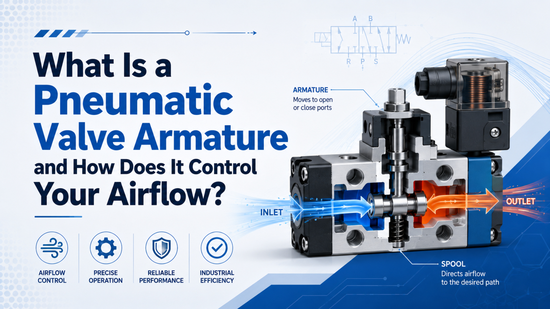
A pneumatic valve armature is the moving magnetic part of a solenoid assembly. When the coil is energized, magnetic force pulls the armature toward a fixed pole. That movement may open the main valve seat directly or open a pilot passage that shifts a larger diaphragm, piston, or spool.
The armature therefore starts the airflow change, but it does not always carry the main flow. A click proves that something moved inside the solenoid. It does not prove that the main valve shifted, the correct port pressurized, or the actuator received enough flow to move.
Key Takeaways
- Parker identifies 3 basic solenoid-valve components: the solenoid, valve body, and plunger or armature (Parker).
- A direct-acting armature controls the main seat; a pilot armature controls a smaller pilot passage.
- Diagnose command, coil current, armature motion, valve switching, and port pressure as separate events.
- Replace an armature only when the exact valve documentation permits it and all interfaces match.
What Exactly Is a Pneumatic Valve Armature?
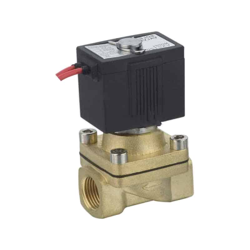
Parker describes 3 basic parts in a typical solenoid valve: the solenoid, the valve body, and the plunger or armature (Parker solenoid-valve operating principles, accessed July 22, 2026). The armature is the ferromagnetic moving member that converts the coil’s magnetic field into short linear travel.
Terminology varies by manufacturer. One catalog may call the moving magnetic part a plunger. Another may reserve armature for the magnetic core and use plunger, stem, or operator for the part that carries the seal. A replacement decision must follow the exploded drawing and parts list for the installed model, not a generic label.
| Term | Typical function | What to verify on the exact valve |
|---|---|---|
| Coil | Creates magnetic flux when current flows | Voltage, AC/DC, frequency, duty rating, connector, suppression |
| Fixed pole or stop | Completes part of the magnetic path | Surface condition, air gap, shading ring where applicable |
| Armature or plunger | Moves in response to magnetic force | Diameter, stroke, guidance, residual magnetism, orientation |
| Return spring | Establishes the de-energized position | Free length, rate, preload, corrosion, installation direction |
| Seal or seat insert | Closes a main or pilot orifice | Material, geometry, swelling, indentation, media compatibility |
| Core or armature tube | Contains and guides the moving magnetic member | Bore condition, straightness, contamination, pressure boundary |
The armature is commonly made from a magnetically responsive alloy, but “stainless steel” alone is not a quality grade or compatibility specification. Magnetic permeability, corrosion resistance, residual magnetism, surface finish, hardness, and machinability all influence performance. Seal material and fluid compatibility are separate decisions.
The spring does not automatically make a valve normally closed. The valve’s seat arrangement and porting determine whether spring return blocks, opens, pressurizes, or exhausts a passage. Read the pneumatic symbol before inferring the de-energized airflow state.
Direct-Acting Armature Control of the Main Airflow
Bürkert identifies 3 opposing load groups for a direct-acting solenoid: spring force plus static and dynamic pressure forces (Bürkert direct-acting valves, accessed July 22, 2026). The energized armature must produce enough travel and net magnetic force to move the main sealing element against those loads.
In a normally closed direct-acting valve, the de-energized spring holds the sealing element against the main orifice. Energizing the coil builds magnetic flux across the working air gap. Once magnetic force exceeds the opposing forces, the armature moves and lifts the seal. Flow then follows the port connection shown by the valve symbol.
The reverse sequence occurs when power is removed. Coil current decays, magnetic force falls, and the return spring drives the armature toward its normal position. The seal must contact the seat with enough force to meet the specified external-leakage limit. Residual magnetism, contamination, a swollen seal, or a damaged guide surface can slow or prevent release.
The useful diagnostic boundary is seat movement, not sound. A sharp click can occur before full stroke, and a partly lifted seal may pass some air without delivering the catalog flow. Conversely, a small direct-acting operator may shift quietly even though the valve is working normally.
Direct-acting valves do not need pilot pressure to initiate movement, but differential pressure still changes the force at the seat. A valve that switches during a no-pressure bench test may fail to open at the machine’s actual inlet pressure if the coil, spring, or orifice does not match the application.
For the magnetic-force side of this relationship, see the solenoid plunger force calculation guide. Use the manufacturer’s force-stroke and pressure data for final selection.
What Changes in a Pilot-Operated Solenoid Valve?
Parker’s operating-principle guide separates 2 relevant arrangements: direct operation and pilot operation (Parker, accessed July 22, 2026). A pilot-operated valve has 2 mechanical events. The armature changes a small pilot passage first, then pressure imbalance moves the main diaphragm, piston, or spool.
This architecture lets a relatively small solenoid control a larger main flow path. It also adds conditions that a direct-acting valve does not share. The pilot passage must be clear, the required pressure differential must exist unless the design is externally piloted or assisted, and the main moving element must be free to travel.
| Diagnostic stage | Direct-acting valve | Pilot-operated valve |
|---|---|---|
| Electrical command | Energizes the coil | Energizes the coil |
| Armature action | Moves the main seal or poppet | Opens or closes the pilot orifice |
| Pressure dependency | Pressure changes the seat load | Pilot pressure moves the main element |
| Main-flow action | Begins with armature travel | Begins only after the main element shifts |
| Common hidden fault | Insufficient magnetic force or seat obstruction | Blocked pilot path, low pilot pressure, or stuck main element |
What does this mean on a stopped machine? If the armature clicks but the outlet port does not pressurize, the solenoid stage may be healthy while the pilot or main stage remains stationary. Replacing the coil would not clear a blocked pilot hole or restore a damaged diaphragm.
An armature fault and a main-valve fault can produce the same external symptom. The fastest separation test is to record coil voltage, inlet pressure, pilot requirement, and outlet-port pressure during the same command. Those measurements show where the command-to-airflow chain stops.
The broader pilot-operated valve guide explains internal and external pilot arrangements. Do not assume that every pilot valve can shift from zero differential pressure.
Why Can the Armature Click Without Producing Airflow?
A 2/2 valve has two ports and two switching positions, while a 3/2 valve has three ports and two switching positions; the armature only initiates the connection defined by the symbol (Parker, accessed July 22, 2026). Hearing a click does not identify which port actually opened or closed.
Treat the valve as a sequence of testable boundaries:
controller output -> voltage at connector -> coil current -> magnetic force
-> armature travel -> pilot or main-element travel -> port pressure -> actuator motion
Each boundary can fail independently. An indicator LED may light even when voltage at the loaded coil is too low. The armature may move only part of its stroke. A pilot valve may vent its control chamber without shifting the main spool. The outlet may pressurize correctly while an undersized fitting, clogged muffler, or downstream leak prevents useful actuator motion.
| Observation | What it proves | What it does not prove |
|---|---|---|
| Output LED turns on | A command or indicator circuit is active | Rated voltage reaches the coil under load |
| Coil becomes magnetic | Current creates some magnetic field | Armature completed its stroke |
| Audible click | A mechanical impact occurred | Main valve or correct port switched |
| Manual override works | Main valve and air path can move under that test | Coil, wiring, and automatic pilot action are healthy |
| Outlet pressure rises | The commanded pneumatic path opened | Flow is adequate for the required cycle time |
| Actuator moves | Some useful flow reached the load | Valve timing, leakage, and force margin meet specification |
First confirm the valve symbol, port numbering, and normal state. A 3/2 valve may connect its working port to exhaust when de-energized; a 5/2 valve routes pressure and exhaust differently. Testing the wrong port can make a correctly shifting valve look blocked.
For a full port-level explanation, read how pneumatic solenoid valves control compressed air. For a symptom-driven workflow, use the solenoid valve troubleshooting guide.
Which Symptoms Actually Point to an Armature Problem?
Emerson publishes a response time of about 20 ms for specified Series 275 and 375 configurations, not for every pneumatic solenoid valve (Emerson ASCO Series 275/375 catalog, accessed July 22, 2026). A change in timing is meaningful only when voltage, pressure, temperature, and measurement conditions are comparable.
| Symptom | Armature-related possibility | Other causes to exclude first |
|---|---|---|
| No click | Armature seized, excessive gap, broken spring | No command, low voltage, open coil, wrong coil, failed driver |
| Click but no port change | Incomplete armature stroke, blocked pilot seat | Low pilot pressure, stuck main spool, wrong port, blocked supply |
| Intermittent sticking | Debris, corrosion, swollen insert, burr, residual magnetism | Connector fault, voltage drop, pressure fluctuation, icing |
| Continuous AC buzz | Incomplete pull-in, damaged shading feature, unstable supply | Wrong frequency, loose coil or hardware, low voltage under load |
| Slow release | Contamination, residual magnetism, weak or damaged spring | DC suppression delaying current decay, trapped pilot pressure |
| External or seat leakage | Damaged armature seal or seat contamination | Cracked body, damaged diaphragm, worn spool seals, bad fitting |
| Hot coil | Incomplete AC pull-in may raise current | Normal continuous-duty heat, high ambient temperature, overvoltage |
Coil temperature alone is weak evidence. Emerson’s ASCO instructions warn that a continuously energized solenoid can become hot during normal operation (ASCO Series 210 installation instructions, accessed July 22, 2026). Compare measured voltage, current, ambient temperature, duty rating, and stabilized temperature with the model documentation.
The electrical behavior also depends on coil type. An AC solenoid commonly draws higher current while the magnetic gap is open; contamination that prevents full pull-in can therefore sustain abnormal current and buzzing. A DC coil’s steady current is mainly resistance-limited, so a stuck armature does not automatically create the same inrush-current condition.
Some DC drivers deliberately apply a high pickup current and then reduce it to a lower hold current. Parker’s hit-and-hold guidance describes this separation between actuation and holding current (Parker hit-and-hold white paper, 2020). Driver behavior must be included before interpreting a current trace.
The AC-versus-DC solenoid response guide covers inrush and pickup differences. The coil-inductance guide explains why pickup and release timing can change even when the valve body is unchanged.
Safe Armature Diagnosis at the Machine
OSHA 29 CFR 1910.147 requires control of hazardous energy during servicing and maintenance (OSHA lockout/tagout standard, accessed July 22, 2026). That requirement covers more than electrical isolation. Stored pneumatic pressure and gravity-loaded or spring-loaded machine motion can remain hazardous after the coil is de-energized.
Use the machine’s approved energy-control procedure before disconnecting wiring, removing a coil, opening an armature tube, loosening a valve body, or separating an air line. Exhaust and verify stored pressure. Mechanically support loads that could fall or drift. A manual override is a commissioning aid, not an isolation device.
Then diagnose in layers:
- Identify the valve. Record manufacturer, complete model code, pneumatic symbol, port labels, coil voltage, AC/DC and frequency, pressure range, pilot arrangement, medium, mounting orientation, and connector or suppression circuit.
- Record the symptom under controlled conditions. Note inlet pressure at the valve during the command, outlet-port pressure, ambient and medium temperature, command duration, cycle rate, and whether the fault affects pickup, hold, or release.
- Check the electrical boundary. Measure voltage at the coil while commanded, not only at the power supply. With energy isolated, compare coil resistance and insulation checks with the manufacturer’s limits. Do not apply an arbitrary resistance limit across different coil designs.
- Check the magnetic and mechanical boundary. Use current or a manufacturer-approved magnetic indication method. A field proves current flow, not full armature stroke. Listen and feel only from a safe position.
- Check the pneumatic boundary. Measure inlet, pilot, working-port, and exhaust behavior as applicable. Confirm that supply pressure remains within the valve’s documented operating range during flow.
- Inspect only when the model is serviceable. Follow the manufacturer’s disassembly instructions. Look for particles, varnish, corrosion, damaged guide surfaces, a distorted seal insert, a broken spring, seat damage, and debris in the pilot passage.
In our experience, the best troubleshooting record is a synchronized set of command, coil voltage or current, inlet pressure, and outlet pressure. It distinguishes an electrical dropout from incomplete armature travel, a pilot-pressure failure, a stuck main element, or a downstream restriction without relying on sound alone.
Never energize a removed coil unless the manufacturer explicitly permits the test and defines its limits. Some coils depend on the installed magnetic circuit and mounting for current behavior or heat transfer. Never probe live equipment in a hazardous location with instruments that lack the required approval.
Can You Replace Only the Armature Assembly?
Parker’s 3-component description explains valve construction, but it does not establish that all 3 components are separately serviceable (Parker, accessed July 22, 2026). Replace only the armature assembly when the exact manufacturer identifies a compatible service kit and permits field repair for that valve, medium, location, and approval.
“It fits in the tube” is not a compatibility test. Check every interface below:
| Compatibility item | Evidence required |
|---|---|
| Valve identity | Complete manufacturer, series, function, revision, and orifice code |
| Magnetic interface | Armature diameter, working gap, pole geometry, material, stroke, and residual-magnetism behavior |
| Mechanical interface | Tube bore, guide length, spring dimensions and rate, retainers, installation direction |
| Sealing interface | Insert profile, seat diameter, surface condition, shutoff direction, allowable leakage |
| Pneumatic rating | Working-pressure range, minimum differential, proof pressure, pilot source, flow direction |
| Medium compatibility | Compressed-air quality, lubricant policy, moisture, temperature, and seal compatibility |
| Electrical match | Coil voltage, AC/DC, frequency, power, duty rating, driver, rectifier, suppression |
| Compliance | Hazardous-location, functional-safety, hygiene, material, and regional approvals |
Replace the complete valve when the armature tube is bent, corroded, scored, or part of a non-serviceable pressure boundary; when the seat or valve body is damaged; when the main diaphragm or spool has failed; or when no approved kit and procedure exist. Mixing certified coils, operators, and bodies can invalidate an assembly approval even if the parts appear to fit.
After repair, perform the manufacturer’s leakage, function, electrical, pressure, and cycle checks before returning the machine to service. Confirm both energized and de-energized port states. If the valve performs a risk-reduction function, use the validation procedure defined by the machine’s safety design rather than treating a successful bench cycle as sufficient.
Use the OEM solenoid-valve compatibility checklist when the original kit is unavailable or a complete substitute valve is being considered.
How Should You Verify Armature-to-Airflow Performance?
ISO 12238:2023 devotes 17 pages to measuring shifting time for applicable two- and three-position directional valves (ISO 12238:2023, 2023). That level of definition matters because coil current, first armature motion, completed valve shift, outlet-pressure change, and actuator arrival are different events with different acceptance limits.
Define the output that matters before testing. If the complaint is “slow valve,” specify whether the limit applies to electrical pickup, mechanical shift, port-pressure rise, full flow, or machine-sensor arrival. Record supply pressure, downstream volume, exhaust hardware, medium and ambient temperature, command voltage, measurement threshold, and direction of switching.
A practical acceptance test should cover:
- cold start and thermally stabilized operation;
- minimum, nominal, and maximum documented pressure conditions;
- pickup, hold, and release in both required flow states;
- leakage in each de-energized and energized seat condition;
- repeated cycling at the production command duration and duty cycle;
- outlet pressure at the valve and, when relevant, at the actuator;
- command loss and pressure restoration under the machine’s approved procedure.
Do not borrow a 20 ms catalog value from another valve family. Compare the repaired or replacement valve with the installed requirement and the correct test method. If the process limit is actuator arrival, include tubing, fittings, mufflers, flow controls, cylinder volume, load, and sensor location in the result.
Pneumatic Valve Armature FAQs
Emerson documents about 20 ms response for particular Series 275 and 375 configurations, while Parker separates direct and pilot operating principles (Emerson; Parker, accessed July 22, 2026). These model and architecture differences explain why armature behavior cannot be judged from a generic click or universal timing claim.
Is a valve armature the same thing as a plunger?
Sometimes, but not universally. Many catalogs use armature and plunger for the same moving magnetic member. Others distinguish the magnetic armature from a stem, operator, or sealing plunger attached to it. Use the exact model’s sectional drawing, bill of materials, and service-kit terminology before ordering parts.
Can an armature click even when the valve does not open?
Yes. A click confirms a mechanical impact, not full travel or correct port switching. The armature may move partly, a pilot orifice may remain restricted, or the main diaphragm or spool may stay in place. Check coil voltage, pilot conditions, inlet pressure, outlet pressure, and exhaust behavior during the same command.
Why does an AC solenoid buzz when the armature sticks?
An open magnetic gap can keep AC coil current above its fully seated condition and make the magnetic pull pulsate. Dirt, low loaded voltage, mechanical damage, or a faulty shading feature may prevent complete pull-in. Isolate the equipment and follow the model’s service procedure; buzzing does not identify one cause by itself.
Does normally closed mean the valve is safety-rated?
No. Normally closed describes the valve’s port state without electrical power. It does not prove monitored operation, diagnostic coverage, required performance level, safe exhaust behavior, resistance to common-cause failure, or suitability for a hazardous load. The machine risk assessment and validated safety architecture determine whether the valve performs a safety function.
Can I replace only a worn armature instead of the whole valve?
Only when the manufacturer permits service and lists a compatible armature kit. Verify valve code, tube, stroke, spring, seat, seal material, pressure range, medium, coil, orientation, and approvals. Replace the complete valve if the pressure boundary or seat is damaged, the assembly is non-serviceable, or compatibility cannot be documented.
Sources and technical references
- Parker, Solenoid Valves: Operating Principles and Construction, construction, direct operation, and pilot operation. Accessed July 22, 2026.
- Bürkert, Valves, Direct-Acting, armature force against spring and pressure forces. Accessed July 22, 2026.
- Emerson ASCO Series 275/375 catalog, model-specific response-time example. Accessed July 22, 2026.
- Emerson ASCO Series 210 installation instructions, installation, maintenance, and normal solenoid heating. Accessed July 22, 2026.
- Parker, Hit and Hold Control for Solenoid Valves, actuation current, holding current, and heat reduction. 2020.
- ISO 12238:2023, directional-control-valve shifting-time measurement. 2023.
- OSHA 29 CFR 1910.147, control of hazardous energy during service and maintenance. Accessed July 22, 2026.