

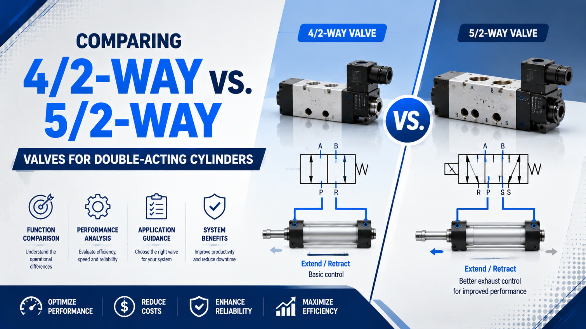
Both 4/2-way and 5/2-way directional valves can reverse a double-acting pneumatic cylinder. The deciding difference isn’t whether the cylinder can extend and retract. It is how the exhausting chamber connects at the valve: a 4/2 uses one common exhaust, while a 5/2 provides two valve-side exhaust ports.
That extra port is useful when the two exhaust paths need different silencers, restrictions, collection lines, or diagnostic points. It does not make a 5/2 automatically more accurate, faster, or safer. Those results depend on the complete circuit, including flow capacity, tubing, speed controls, actuator type, operating pressure, and valve return behavior.
Key Takeaways
- A 4/2 has 4 ports and 2 states; a 5/2 has 5 ports and 2 states.
- Either valve can support separate extend and retract speed settings when one-way flow controls are fitted at both cylinder ports.
- Choose 5/2 when the two valve-side exhaust paths require separate treatment.
Short Answer: Both Can Control a Double-Acting Cylinder
Parker describes a 4-port valve with pressure, two cylinder ports, and one common exhaust, and a 5-port valve with the same pressure and cylinder connections plus two dedicated exhausts (Parker Pneumatic Valve Fundamentals). Both arrangements provide the two alternating flow states required by a double-acting cylinder.
In one state, supply air enters the cap-end chamber while the rod-end chamber exhausts. In the other state, those connections reverse. A 4/2 and a 5/2 therefore perform the same basic directional task. The port count changes the exhaust architecture, not the number of cylinder directions.
So why is 5/2 common in industrial automation? Separate exhaust ports make valve-mounted silencers and exhaust restrictions direction-specific. They also suit manifolds designed around five-port interfaces. A 4/2 remains technically sound when a common exhaust is acceptable and every other specification matches the application.
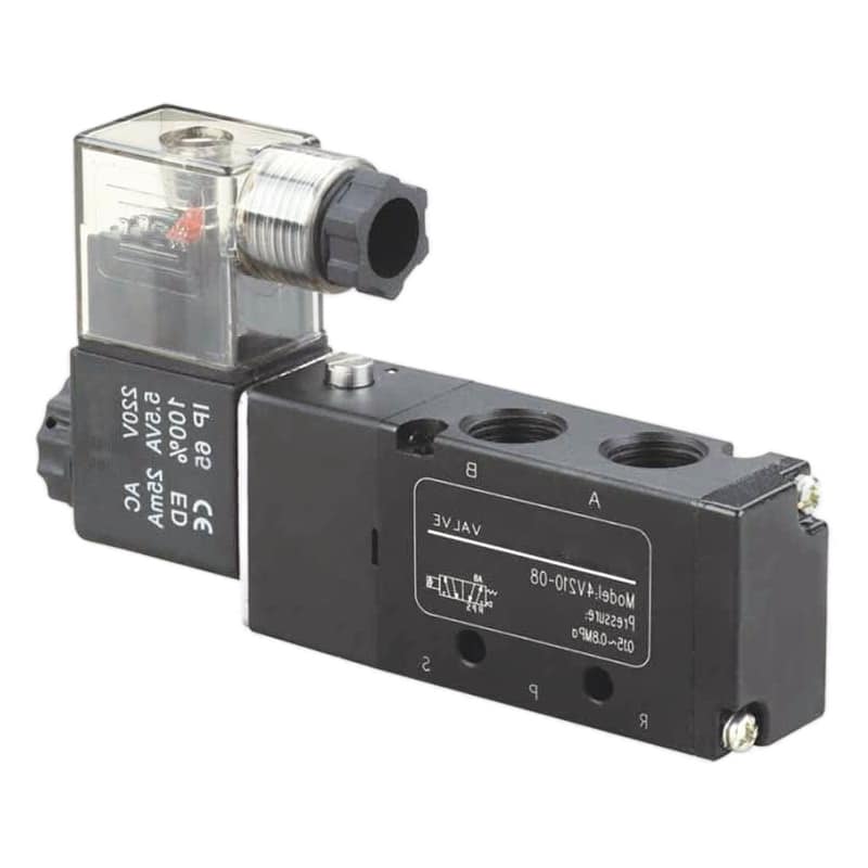
The physical appearance alone doesn’t reveal the internal flow function. Read the datasheet state diagram, port markings, actuator symbols, and model code before ordering or connecting a valve.
What Do 4/2 and 5/2 Actually Mean?
ISO 1219 separates fluid-power symbol construction from circuit-diagram use across two documents: ISO 1219-1 contains 178 pages, while ISO 1219-2 contains 42. In slash notation, the first number counts main flow ports and the second counts discrete switching positions.
| Designation | Supply ports | Work ports | Exhaust ports | Switching positions |
|---|---|---|---|---|
| 4/2 | 1 | 2 | 1 common exhaust | 2 |
| 5/2 | 1 | 2 | 2 separate exhausts | 2 |
A 4/2-way valve is a directional valve with four main flow ports and two switching positions. A 5/2-way valve is the five-port counterpart, retaining two positions while separating the two valve-side exhaust paths.
Common numeric markings are 1 for pressure supply, 2 and 4 for the cylinder work ports, and 3 plus 5 for exhaust. Letter markings such as P, A, B, R, S, EA, or EB may also appear. ISO 11727 covers identification and marking rules, but the manufacturer’s drawing remains the connection authority for a specific valve.
The notation does not reveal everything. It doesn’t state whether the valve is solenoid-, air-, or manually operated; whether it is monostable or bistable; what pressure and flow it can handle; or which state is normal. For a detailed symbol-reading method, use the guide to ISO 1219 pneumatic valve symbols.
One catalog-language trap deserves attention. Some North American documents call both configurations “4-way” valves because each performs a four-way directional function, then distinguish four-port from five-port construction. The slash forms 4/2 and 5/2 avoid that ambiguity by stating physical port count and position count explicitly.
How Do Their Flow Paths Differ in Each Position?
Parker’s five-port state description connects 1 to 2 while 4 exhausts through 5, then connects 1 to 4 while 2 exhausts through 3; its four-port version sends either work port to one shared exhaust. These 2-state tables expose the functional difference more reliably than housing shape or connector count.
| Valve state | 4/2 active paths | 5/2 active paths |
|---|---|---|
| State A | P to A; B to common E | 1 to 2; 4 to 5 |
| State B | P to B; A to common E | 1 to 4; 2 to 3 |
The diagram is functional, not a universal mounting view. A manufacturer may mirror the symbol, rotate the body, or use different letters. Spring and actuator symbols identify how the valve reaches each state. Never assume that the left-hand symbol box is energized or that a particular housing port is supply.
What happens when power is removed? A single-solenoid, spring-return valve moves to its defined spring state. A double-solenoid or detented valve may retain its last state. That behavior can matter more than whether the body has four or five ports.
Can a 4/2 Valve Control Extend and Retract Speed Independently?
Yes. A double-acting cylinder has 2 work ports, so fitting one one-way flow control at each cylinder connection provides two separately adjustable meter-out paths. SMC recommends controlling cylinder speed by metering exhaust flow and notes that tubing and port sizes also influence achievable speed (SMC).
During extension, the rod-end chamber exhausts through its local flow control before that air reaches the valve. During retraction, the cap-end chamber exhausts through the other control. In a 4/2 circuit, the two flows join only after their direction-specific restrictions. The common exhaust does not erase those independent settings.
The confusion usually comes from putting a throttle or restrictive silencer only at the 4/2 valve’s common exhaust. That single downstream restriction affects whichever chamber is exhausting, so it influences both directions. Move the speed controls to the actuator ports and use the correct one-way orientation. For a deeper comparison, see meter-in versus meter-out control.
This distinction separates two different design questions. Cylinder-port controls set motion direction by direction. Valve-exhaust accessories manage what happens after air leaves the directional valve. A 5/2 gives more freedom for the second question, but it isn’t a prerequisite for the first.
Watch for exceptions. Meter-out control can be unsuitable when the actuator must move with very low back pressure, when a special quick-exhaust arrangement bypasses the valve, or when the load can overrun the actuator. Treat those as circuit-design cases, not as proof that one port count is universally superior.
When Do Separate Exhaust Ports Actually Matter?
A 5/2 provides 2 valve-side exhaust ports instead of the 4/2 valve’s single common exhaust, according to Parker’s connector handbook (Parker). Choose that arrangement when exhaust treatment must differ by direction or when the selected manifold and valve family are built around five-port routing.
Separate exhausts are useful in these cases:
- Different valve-mounted restrictions. One direction may need additional exhaust throttling at the valve, although cylinder-port meter-out controls are usually easier to reason about.
- Different silencers or back-pressure limits. A heavily loaded silencer on one path need not affect the opposite path.
- Exhaust capture. Air from one chamber can be routed to a collection, recovery, or cleaner discharge point without combining it with the other chamber.
- Directional diagnostics. Separate pressure or flow measurements can reveal which motion direction is generating unusual restriction.
- Manifold standardization. A machine platform may already use a five-port valve island, connector pattern, or spare-parts family.
Would separate ports improve a simple clamp with identical speeds and one acceptable discharge point? Probably not by themselves. If a 4/2 meets the flow, pressure, leakage, electrical, environmental, mounting, and fail-state requirements, the extra exhaust port may add no practical value.
Other Specifications That Decide the Selection
ISO 6358-1 devotes 61 pages to steady-state testing of compressible-fluid component flow characteristics, while ISO 12238:2023 uses 17 pages for pneumatic valve shifting-time tests (ISO 6358-1; ISO 12238). That scope shows why port count alone cannot predict cylinder speed or response.
Compare these items on the exact part number:
| Requirement | What to verify | Why it matters |
|---|---|---|
| Flow capacity | Sonic conductance, critical pressure ratio, or the manufacturer’s stated flow metric and test conditions | Determines pressure loss and available cylinder flow |
| Pressure range | Supply, pilot, and exhaust-pressure limits | Pilot-operated valves may not shift below minimum pressure |
| Valve state | Spring return, detent, or double solenoid | Defines behavior after a command or power change |
| Internal leakage | Datasheet maximum and test condition | Affects holding, drift, air use, and diagnostics |
| Switching time | Test method, pressure, voltage, and load | Valve response is only one part of cylinder stroke time |
| Electrical data | Coil voltage, power, duty, suppression, connector, ingress rating | Must match the control output and environment |
| Interface | Standalone ports, sub-base, manifold standard, thread, and envelope | Governs installation and replacement |
| Media and seals | Air quality, temperature, lubricant, and elastomer compatibility | Prevents swelling, wear, sticking, or corrosion |
Don’t size a valve from a generic Cv equation copied without test conditions. Gas flow can become choked, and catalogs may publish Cv, Kv, sonic conductance, normal flow, or standard flow under different conventions. Use comparable data and then check the whole restriction chain. Our pneumatic valve sizing guide covers that workflow.
Cylinder force and speed are also different questions. Pressure and effective piston area govern theoretical force; available flow and system restriction govern motion rate. The guide to flow versus pressure sizing keeps those decisions separate.
Neither port count makes a valve inherently safe. A spring-return valve has a defined de-energized state, while a bistable valve can retain its last commanded state. The machine risk assessment must decide whether motion should stop, vent, remain pressurized, or move to a defined position. If a center state is required, review 5/3 valve center conditions instead of treating a 5/2 as a mid-stroke holding device.
A Practical 4/2 vs. 5/2 Selection Checklist
ISO 11727’s 11-page scope covers identification for main-flow, control, pilot-supply, and solenoid connections, and ISO confirmed the standard again on 2026-05-20 (ISO 11727). Use those markings with the datasheet, then document every connection and state before approving the valve.
In application reviews, we’ve found that a written state table catches more selection mistakes than starting with a familiar series or valve-body shape. Use the following sequence to keep the functional decision separate from brand, mounting, and procurement preferences.
- Confirm the actuator function. A double-acting cylinder normally needs two alternating work-port connections. If the application is single-acting, compare 3/2 and 5/2 application roles instead.
- Write a two-row state table. Record supply, exhaust, and blocked paths for each switching state.
- Decide where speed is controlled. For ordinary meter-out control, plan one correctly oriented one-way flow control at each cylinder port.
- Define exhaust treatment. If each direction needs a separate silencer, throttle, collection line, or test point, prefer 5/2.
- Define loss-of-command behavior. Specify monostable or bistable operation from the risk assessment, not convenience.
- Check the flow path. Include valve, manifold, fittings, tubing, speed controls, quick exhausts, and silencers.
- Verify operating limits. Check supply and pilot pressure, temperature, media, leakage, voltage, duty, protection, and switching data.
- Check installation compatibility. Confirm thread standard, port size, manifold interface, connector, envelope, manual override, and spare-parts policy.
- Commission with measurements. Record pressure at the valve and cylinder during motion, then set the two direction-specific flow controls.
The shortest reliable RFQ doesn’t ask only for “a 5/2 valve.” It states the required two flow states, normal or retained state, supply and pilot range, flow target, coil and connector, interface, environment, and exhaust treatment. That description lets a supplier propose an equivalent function without hiding a critical assumption.
4/2-Way vs. 5/2-Way Valve FAQs: What Should Engineers Ask?
Parker’s 4-port and 5-port descriptions identify the same 2 cylinder work connections in both designs; the difference is 1 common exhaust versus 2 separate exhausts. The FAQs below apply that distinction to speed control, replacement, exhaust treatment, and the point at which a three-position valve becomes the better question.
Can a 4/2 valve independently control extension and retraction speed?
Yes. Install one correctly oriented one-way flow control at each of the cylinder’s 2 ports. Each device then meters the chamber that exhausts during its associated stroke and allows freer inlet flow in the opposite direction. A throttle installed only on the common valve exhaust is different because it restricts both directional exhaust paths.
Why does a 5/2 valve have two exhaust ports?
The two exhaust ports keep the work-port return paths separate at the valve. This allows direction-specific silencers, exhaust restrictions, collection lines, or diagnostic measurements. It can also match a standard five-port manifold interface. Those benefits concern valve-side exhaust handling; they don’t prevent a 4/2 circuit from using two independent cylinder-port speed controls.
Is a 5/2 valve always better than a 4/2 valve?
No. A 5/2 is more flexible when exhaust paths need separate treatment, but performance still depends on flow capacity, pressure range, leakage, switching state, electrical data, interface, and the rest of the circuit. A compliant 4/2 can be the simpler choice when one common exhaust is acceptable and all application requirements are met.
Can a 4/2 and 5/2 valve replace each other directly?
Not automatically. Both can reverse a double-acting cylinder, but their porting, manifold interface, envelope, thread, flow data, pilot requirements, coil, connector, and failure behavior may differ. Before substitution, build a state table for both parts and compare every datasheet limit. Re-plumb the exhaust only after confirming the machine’s required behavior.
When should I choose a 5/3 valve instead?
Choose a 5/3 when the circuit genuinely needs a third commanded state, such as a defined center-exhaust, center-pressure, or center-closed condition. The center function must match the risk assessment. Closed center can still drift through leakage and air compressibility, while pressure center does not automatically balance a single-rod cylinder’s unequal piston areas.
Sources and technical references
- ISO 1219-1:2012, graphical symbols and rules for fluid-power systems and components. Retrieved 2026-07-26.
- ISO 1219-2:2012, rules for fluid-power circuit diagrams. Retrieved 2026-07-26.
- ISO 11727:1999, identification of valve ports, control mechanisms, solenoid leads, and related connections. Retrieved 2026-07-26.
- ISO 6358-1:2013, steady-state testing for compressible-fluid component flow-rate characteristics. Retrieved 2026-07-26.
- ISO 12238:2023, test procedures for pneumatic directional-control valve shifting time. Retrieved 2026-07-26.
- Parker: Pneumatic Valve Fundamentals, four-port and five-port directional-valve flow paths. Retrieved 2026-07-26.
- Parker: Pneumatic Connectors Handbook, 4/2 and 5/2 port and exhaust descriptions. Retrieved 2026-07-26.
- SMC: Control Air Flow of Cylinders, meter-out speed-control guidance and system flow considerations. Retrieved 2026-07-26.
- AutomationDirect: Understanding Pneumatic Valve Ports and Ways, video background for pneumatic valve port and position terminology. Retrieved 2026-07-26.