

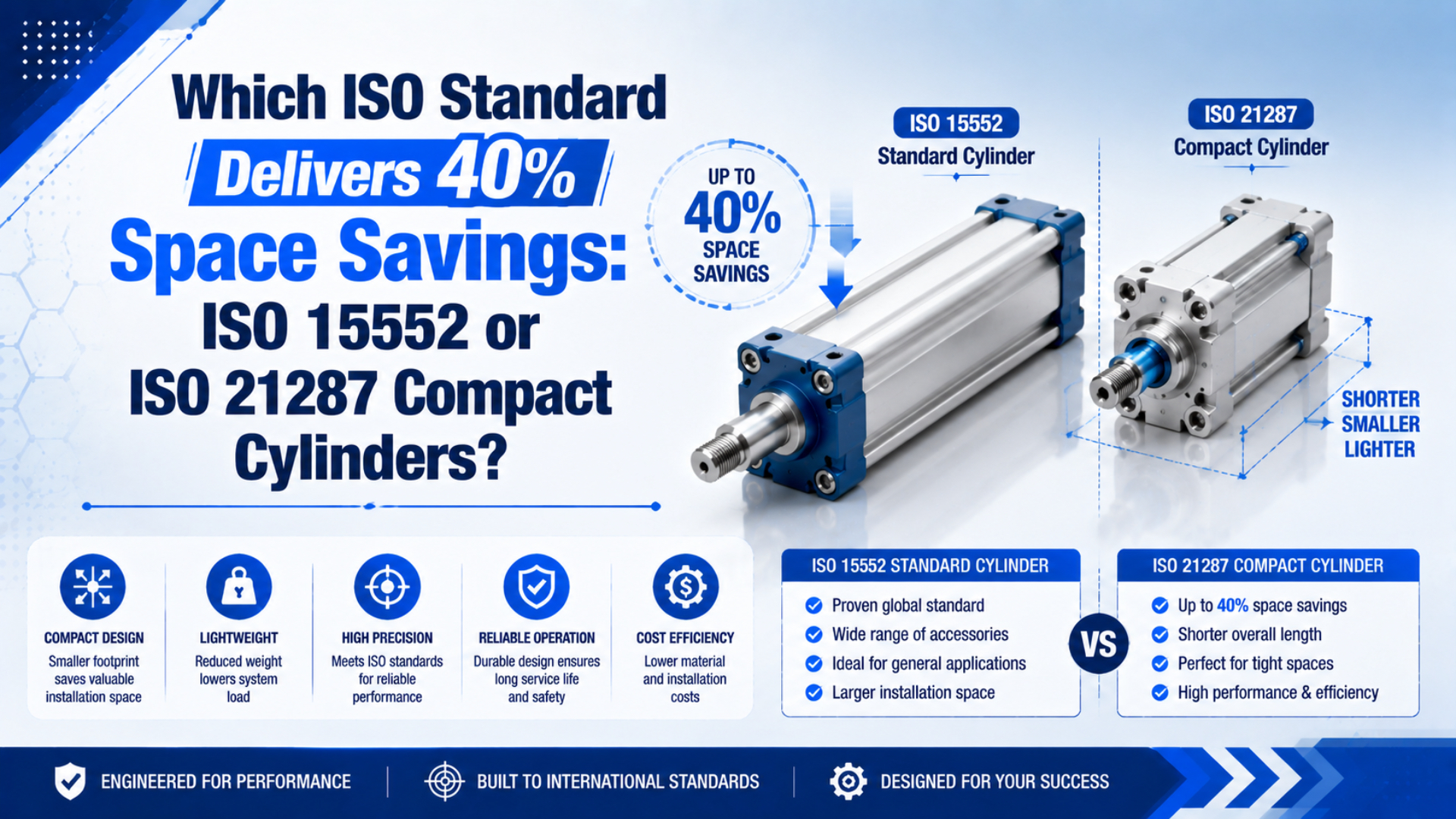
ISO 21287 is the compact-cylinder standard, but neither ISO 21287 nor ISO 15552 guarantees a universal 40% space saving. The actual reduction must be calculated from two configured supplier drawings at the same bore, stroke, rod arrangement, and mounting reference. A short body helps only if fittings, sensors, rod hardware, and service clearance still fit.
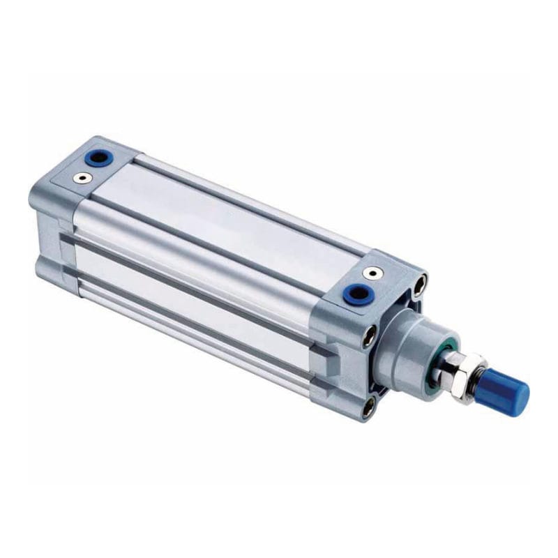
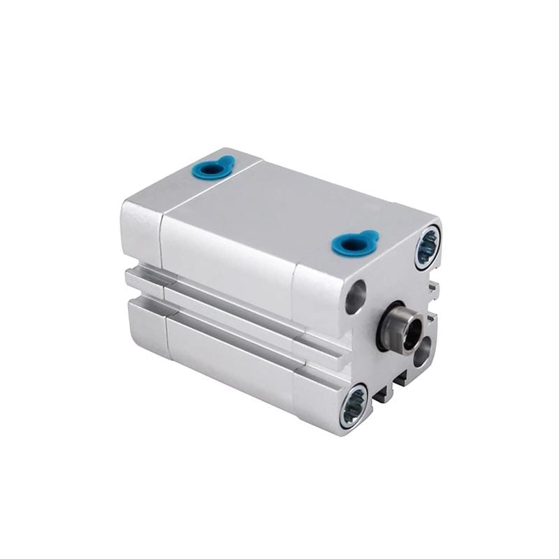
ISO 21287:2004 covers single-rod compact cylinders from 20 to 100 mm bore at a maximum working pressure of 1,000 kPa, or 10 bar. ISO 15552:2018 covers detachable-mount cylinders from 32 to 320 mm bore at a maximum rated pressure of 1,000 kPa. Those scopes establish different dimensional families, not identical product performance (ISO 21287; ISO 15552, confirmed 2026).
Key Takeaways
- ISO 21287 is the shorter-envelope family, but 40% must be proven from configured drawings.
- The standards overlap from 32 to 100 mm bore.
- Equal bore and pressure give equal theoretical extension force, not equal total performance.
- Cushioning, stroke, mounts, ports, sensors, and service access decide the final choice.
The Two Standards Define Different Cylinder Families
ISO 15552 specifies a 32-320 mm detachable-mount series, while ISO 21287 specifies a 20-100 mm single-rod compact series. Both standards use a 1,000 kPa, or 10 bar, pressure boundary in their published scopes. The overlapping bore range is therefore 32-100 mm, not every size offered by either supplier family (ISO, 2018; ISO, 2004).
| Selection boundary | ISO 15552:2018 | ISO 21287:2004 |
|---|---|---|
| Published bore scope | 32-320 mm | 20-100 mm |
| Cylinder arrangement | Single- or double-rod, with detachable mountings | Single-rod compact cylinder |
| Published pressure boundary | Maximum rated pressure 1,000 kPa | Maximum working pressure 1,000 kPa |
| Magnetic provision | With or without provision for magnetic sensors | With or without magnetic function |
| Cushioning statement | Not defined as one universal product configuration on the public scope page | Standard series is not equipped with adjustable cushioning |
| Mounting relationship | Basic, mounting, and accessory dimensions for interchangeability | End-cover mountings for 32-100 mm may follow ISO 15552; rod mountings may follow ISO 8139 and ISO 8140 |
ISO conformity is a dimensional claim within the stated scope. It does not promise the same rod diameter, internal dead volume, friction, seal material, sensor groove, port position, cushioning option, permissible side load, or catalog stroke range across every product.
That distinction prevents a common specification error. A machine drawing should name the standard and the configured product interfaces. For ISO 15552 replacement work, the four-layer interchangeability checklist separates standardized mounting dimensions from supplier-controlled options and machine acceptance tests.
Measure Space Saving from the Configured Drawings
ISO 21287 uses a seven-page compact-cylinder specification covering 20-100 mm bores, whereas ISO 15552 uses an 18-page detachable-mount specification covering 32-320 mm bores (ISO 21287; ISO 15552). Neither public standard description assigns a universal percentage to the difference in installed length, height, volume, or machine footprint.
A 40% saving is a drawing result, not a standard attribute. Decide first which machine dimension is constrained: axial length, cross-section, swept service envelope, mounting volume, or complete station footprint. Then compare that same dimension between two fully configured candidates.
Installed envelope is the complete three-dimensional space required by the cylinder, its accessories, its motion, and the tools needed for adjustment or removal. It is larger than the bare catalog body.
For axial installed length, calculate:
Here, is the axial length reduction, is the installed reference length of the selected ISO 15552 cylinder, and is the installed reference length of the selected ISO 21287 cylinder. Use millimetres for both lengths and the same mounting datums.
For example, if an approved ISO 15552 configuration measures and the functionally acceptable ISO 21287 configuration measures between the same machine datums, then . These numbers are a transparent worksheet example, not catalog dimensions for every 50 mm or 63 mm cylinder.
Compare the Complete Installed Envelope
| Envelope item | Drawing evidence to compare | Why body length alone can mislead |
|---|---|---|
| Axial machine length | Mounting datum to rod-end working point | Rod adapters or longer clevises can consume the saved length |
| Body height and width | Maximum profile and mounting fasteners | A shorter body may be wider than the available pocket |
| Port and fitting envelope | Port location, elbow orientation, tube bend radius | A rear-facing fitting can collide with the frame |
| Sensor envelope | Groove, switch body, connector, cable exit | The switch may project beyond the nominal cylinder body |
| Adjustment access | Cushion screws, flow controls, locknuts | A compact installation still needs a tool path |
| Maintenance withdrawal | Rod, body, and fastener removal direction | A cylinder that fits but cannot be removed increases downtime |
The practical CAD comparison should include the selected mounting brackets, rod-end hardware, fittings, switches, and cable or tube bend radii. Compare both retracted and extended states. If an adapter plate is required, include it before reporting the percentage.
Do Equal Bores Produce Equal Force and Performance?
Festo lists 1,178 N theoretical advance force at 6 bar for both a 50 mm ADN compact cylinder and a 50 mm DSBC ISO cylinder. The same catalog pages show different stroke and cushioning choices, proving that equal theoretical force does not make the two configured products operationally identical (Festo ADN; Festo DSBC, accessed July 19, 2026).
The theoretical extension relationship is:
In this equation, is theoretical extension force, is effective piston pressure, and is bore diameter. If two double-acting cylinders have the same bore and effective pressure, their theoretical extension force is the same before friction and dynamic losses.
Theoretical extension force is the ideal pressure-area result before seal friction, backpressure, guide resistance, and other dynamic losses are deducted.
Actual machine force still depends on point-of-use pressure during motion, seal friction, rod and guide alignment, backpressure, side load, speed, and the supplier’s allowable load data. Retraction force also depends on rod diameter. Use the bore, force, and speed guide before treating bore as a complete performance specification.
Equal bore and stroke also produce the same ideal swept piston volume. A compact body does not automatically save meaningful compressed air per cycle. Differences can arise from rod volume, end clearance, ports, tubing, pressure, and valve timing, so evaluate air consumption from configured product data rather than exterior size. The double-acting cylinder air-use guide covers that separate calculation.
Envelope, Cushioning, and Stroke Change the Decision
ISO 21287 states that its standardized compact series is not equipped with adjustable cushioning, while ISO 15552 covers detachable-mount cylinders up to 320 mm bore. Current supplier families can add options beyond the public standard scope, but those features must be verified by part number rather than inferred from the ISO label (ISO 21287; ISO 15552).
One supplier comparison shows why product data matters. Festo’s 50 mm ADN family lists strokes from 1 to 400 mm and self-adjusting pneumatic end-position cushioning. Its 50 mm DSBC family lists strokes from 1 to 2,800 mm and a broader set of cushioning variants. Those are Festo family limits, not requirements imposed on every ISO 21287 or ISO 15552 manufacturer.
| Decision variable | What usually favours ISO 21287 | What usually favours ISO 15552 | Evidence required |
|---|---|---|---|
| Axial space | Short-stroke station with a hard length limit | Envelope is available or stroke dominates total length | Configured CAD models |
| Bore range | Required bore is 20-100 mm | Required bore exceeds 100 mm | Force calculation and catalog range |
| Stroke | Short or moderate stroke within compact catalog limits | Long stroke or wider standard-stroke availability | Supplier stroke table |
| End-of-stroke energy | External stop, elastic pad, or approved product cushioning is adequate | Adjustable pneumatic cushioning or larger energy capacity is needed | Moving mass, speed, cushion-energy limit |
| Mounting | Direct body mounting or compact-specific accessory fits | Existing detachable ISO 15552 mounting must be reused | Mounting drawings and accessory codes |
| Serviceability | Cylinder can be accessed despite dense packaging | Adjustment and replacement access matter more than body length | Maintenance-envelope review |
Do not use a compact cylinder’s body as the machine guide. If the load creates side force, moment, or rotation, use external guidance or a guided actuator sized for that load. Cushioning deserves a separate energy check; the pneumatic cylinder cushioning guide explains why bore and pressure alone do not determine safe end-of-stroke behaviour.
When Should You Choose ISO 21287?
ISO 21287 covers 20-100 mm single-rod compact cylinders and explicitly allows 32-100 mm sizes to use end-cover mountings in accordance with ISO 15552 (ISO 21287). Choose this family when the application has a verified short-envelope constraint and the selected product still meets stroke, energy, mounting, sensing, port, environmental, and maintenance requirements.
Good candidates include short clamp, stop, eject, gate, cover, and fixture-release motions. Compact cylinders can also reduce robot wrist offset or free inspection space, but the complete tool mass and centre of gravity still control the result. For that application, use the compact-cylinder EOAT design guide.
In our experience reviewing compact-cylinder layouts, the decisive constraint is often not the bare cylinder body. It is the fitting, sensor connector, rod coupler, or tool-access path beside it. Our team found that a section view through the complete installed assembly exposes these conflicts faster than comparing catalog thumbnails.
Approve ISO 21287 only when all of these statements are true:
- the required bore falls inside the selected product’s range;
- the stroke is available without a special design that changes the envelope;
- end-of-stroke energy is within the permitted cushioning or stop capacity;
- mounting fasteners and rod hardware fit the available datums;
- ports, flow controls, sensors, and cables remain accessible;
- the cylinder can be installed and removed without dismantling unrelated machine sections.
When Should You Choose ISO 15552?
ISO 15552 covers 32-320 mm bores and standardizes basic, detachable-mount, and accessory dimensions for interchangeability at up to 1,000 kPa rated pressure (ISO 15552, confirmed 2025). Choose it when long strokes, larger bores, reusable detachable mountings, configurable cushioning, or cross-supplier replacement control matter more than the shortest possible body.
An ISO 15552 cylinder is often the safer baseline for equipment with established mounting brackets, long operating strokes, significant moving energy, or a maintenance strategy built around standardized accessories. Parker’s P1F catalog, for example, lists 32-125 mm bores and strokes from 5 to 2,500 mm within one ISO 15552 supplier family (Parker P1F, 2025).
The longer body is not automatically waste. It may provide the cushion volume, bearing separation, mounting geometry, adjustment access, or option space the duty requires. If impact or rebound already exists, diagnose the cylinder cushion failure branches before replacing the actuator with a shorter body.
Retrofit Decision Checklist
ISO 21287 permits ISO 15552 end-cover mountings for its 32-100 mm bore range, but that shared accessory relationship does not make the cylinder bodies drop-in equivalents (ISO 21287). Overall length, rod projection, port position, sensor groove, cushion access, and fastener path can still move, so every retrofit needs a drawing overlay and machine trial.
An adapter can solve a bolt pattern while erasing the space saving. Include the adapter thickness, fastener heads, alignment features, and tool clearance in before calculating . Otherwise, the reported percentage describes two loose cylinders, not the installed machine.
Use this sequence:
- Record the installed cylinder’s full model code, bore, stroke, rod end, ports, switches, cushioning, and mounting.
- Define the machine datums and the exact constrained envelope.
- Calculate required extension and retraction force from dynamic point-of-use pressure.
- Check moving mass, speed, impact energy, external stops, and permissible cushioning energy.
- Overlay configured 2D drawings or CAD models at both end positions.
- Add fittings, flow controls, tubes, cables, adapters, guards, and removal clearance.
- Confirm sensor logic and switch adjustment range.
- Inspect rod alignment and external guidance before tightening the new mounting.
- Run a controlled first-article test for leakage, force, stroke time, end impact, sensing, and temperature.
- Freeze the accepted drawing, part code, settings, and test record for future purchasing.
For high-density electronics equipment, the PCB compact-cylinder integration guide provides an application-specific check for fixture clearance, board stress, cameras, sensors, and air quality.
What Should the RFQ and Approval Record Contain?
ISO 15552 provides 11 nominal bore sizes from 32 through 320 mm, while ISO 21287 provides five overlapping nominal bores from 32 through 100 mm plus 20 and 25 mm compact sizes (ISO 15552; ISO 21287). An RFQ must identify the chosen family and the configured interfaces rather than asking only for an “ISO cylinder.”
| RFQ field | Required evidence | Approval question |
|---|---|---|
| Standard and edition | ISO 15552:2018 or ISO 21287:2004 | Is the claimed scope current and applicable? |
| Bore and stroke | Configured model code and drawing | Does it meet force and travel requirements? |
| Reference envelope | Retracted, extended, and service dimensions | Is the stated saving measured from common datums? |
| Mounting and rod end | Mounting code, rod thread, accessory drawings | Will existing machine interfaces fit? |
| Ports and fittings | Thread, location, orientation, fitting envelope | Can the air connections be installed and serviced? |
| Cushioning and energy | Cushion type, speed, moving mass, energy limit | Will the cylinder stop safely at production speed? |
| Sensors | Switch type, groove, connector, adjustment range | Will PLC confirmation remain repeatable? |
| Environment | Temperature, air quality, corrosion, washdown | Are seals and materials suitable? |
| Acceptance test | Force, time, leakage, impact, sensing, temperature | What measurable result releases the part? |
From our analysis of the two ISO scopes and current supplier catalogs, the strongest purchasing language separates three evidence owners: the ISO standard controls named dimensions, the configured supplier drawing controls the selected product, and the machine acceptance test controls functional approval. No single label replaces all three.
The About page explains the engineering roles supporting cylinder applications. When a drawing comparison remains unresolved, send the evidence package through the contact page instead of approving a near-match from catalog names alone.
Conclusion: Which ISO Cylinder Standard Saves More Space?
ISO 21287 is the compact standard, covering 20-100 mm bores at up to 1,000 kPa, while ISO 15552 covers detachable-mount cylinders from 32 to 320 mm at the same published pressure boundary (ISO 21287; ISO 15552). ISO 21287 normally wins axial-envelope comparisons, but 40% is valid only when configured drawings prove it.
Choose ISO 21287 for a verified space-limited, short-stroke task whose cushioning, load, mounting, sensing, and maintenance checks pass. Choose ISO 15552 when bore range, long stroke, detachable mounting interchangeability, cushioning options, or service standardization has greater value. Record the comparison dimension and test criteria so the decision survives the next supplier change.
ISO 15552 vs ISO 21287 FAQs: What Should Engineers Ask?
ISO 15552 and ISO 21287 share a 32-100 mm bore overlap and a published 1,000 kPa pressure boundary, but they standardize different cylinder families (ISO 15552; ISO 21287). These questions separate theoretical similarities from the configured evidence needed for selection and retrofit approval.
Does ISO 21287 guarantee 40% space savings?
No. ISO 21287 defines a compact dimensional family, but its public scope does not promise one percentage against ISO 15552. Calculate the reduction from configured drawings at the same bore, stroke, rod arrangement, and machine datums. Include mountings, adapters, fittings, sensors, and service clearance before reporting the result.
Do ISO 15552 and ISO 21287 cylinders produce the same force?
They have the same theoretical extension force when bore and effective piston pressure are equal. Actual force can differ because of seal friction, backpressure, alignment, and operating pressure at the actuator. Retraction force also depends on rod diameter, so compare configured catalog data and measure the application rather than relying on bore alone.
Can an ISO 21287 cylinder directly replace an ISO 15552 cylinder?
Not automatically. ISO 21287 allows ISO 15552 end-cover mountings for 32-100 mm bores, but body length, rod projection, ports, switches, cushioning, and service access can differ. Overlay the configured drawings, include every adapter and fitting, then validate force, timing, leakage, sensing, and end impact on the machine.
Why does ISO 21287 mention no adjustable cushioning?
The ISO 21287 scope states that its standardized compact series is not equipped with adjustable cushioning, which restricts applications that require it. A modern supplier may offer elastic or self-adjusting cushioning in a product based on the standard. Verify the exact part number and energy limit; do not infer the option from the ISO label.
Which standard is usually better for long-stroke applications?
ISO 15552 is usually the stronger starting point because its supplier families commonly offer broader stroke ranges, larger bores, detachable mountings, and adjustable cushioning options. The standard itself does not guarantee every stroke. Confirm the selected catalog range, rod stability, guides, speed, cushioning energy, and installed envelope before approval.
Sources and technical references
- ISO 15552:2018, detachable-mount pneumatic cylinders, 32-320 mm bore, maximum rated pressure 1,000 kPa. Confirmed 2025.
- ISO 21287:2004, single-rod compact pneumatic cylinders, 20-100 mm bore, maximum working pressure 1,000 kPa. Confirmed 2023.
- Festo compact cylinder ADN, 50 mm family, supplier-specific stroke, pressure, and cushioning data. Accessed July 19, 2026.
- Festo ISO cylinder DSBC, 50 mm family, supplier-specific stroke, pressure, force, and cushioning data. Accessed July 19, 2026.
- Festo ADN compact-cylinder catalog, current supplier dimensions and configured variants. March 2026.
- Parker P1F pneumatic-cylinder catalog, ISO 15552 supplier range and configuration data. 2025.
- AutomationDirect: How to Select a Pneumatic Cylinder, embedded cylinder-selection overview. Uploaded April 16, 2021.